
Software test program generation

a software test and test program technology, applied in the field of data processing systems, can solve the problems of increasing the number of potential failure points within failures can arise during the life of the data processing system, and failure detection

Active Publication Date: 2019-06-13
ARM LTD
View PDF11 Cites 9 Cited by
  • Summary
  • Abstract
  • Description
  • Claims
  • Application Information

AI Technical Summary

Benefits of technology

The present patent provides a computer-based method for generating a software test program to test the performance of a data processing apparatus. The method involves identifying a failure in the data processing apparatus, creating a model to simulate the failure, analyzing the model and the original software program to identify the difference caused by the failure, and adding a stimulus program instruction to the software program to create an updated version. This method helps to detect and address performance issues in data processing apparatus, ensuring reliable and accurate testing.

Problems solved by technology

It is known that failures can arise during the life of data processing systems due to factors such as circuit ageing and particle strikes.
However, if there are failures within the target data processing system that change its response to executing program instructions, then these failure will be detected as the result of running the software test program will not match the expected result as determined by the software test program.
As the complexity of data processing systems increases, there is an increase in the number of potential points of failure within those data processing systems, such as stuck-at errors within integrated circuits.
However, this process is time consuming and highly skilled.
Another issue is that with an increased use of synthesis tools in producing final circuit layouts, it can be difficult for even a skilled engineer familiar with the design to write a software test program which will render discoverable a failure within a portion of a circuit which has been generated by the synthesis tools as the particular function of an individual gate or standard cell within such a synthesised portion of the design may not yet be readily determined.

Method used


Image

  • Software test program generation
  • Software test program generation
  • Software test program generation

Examples


example b

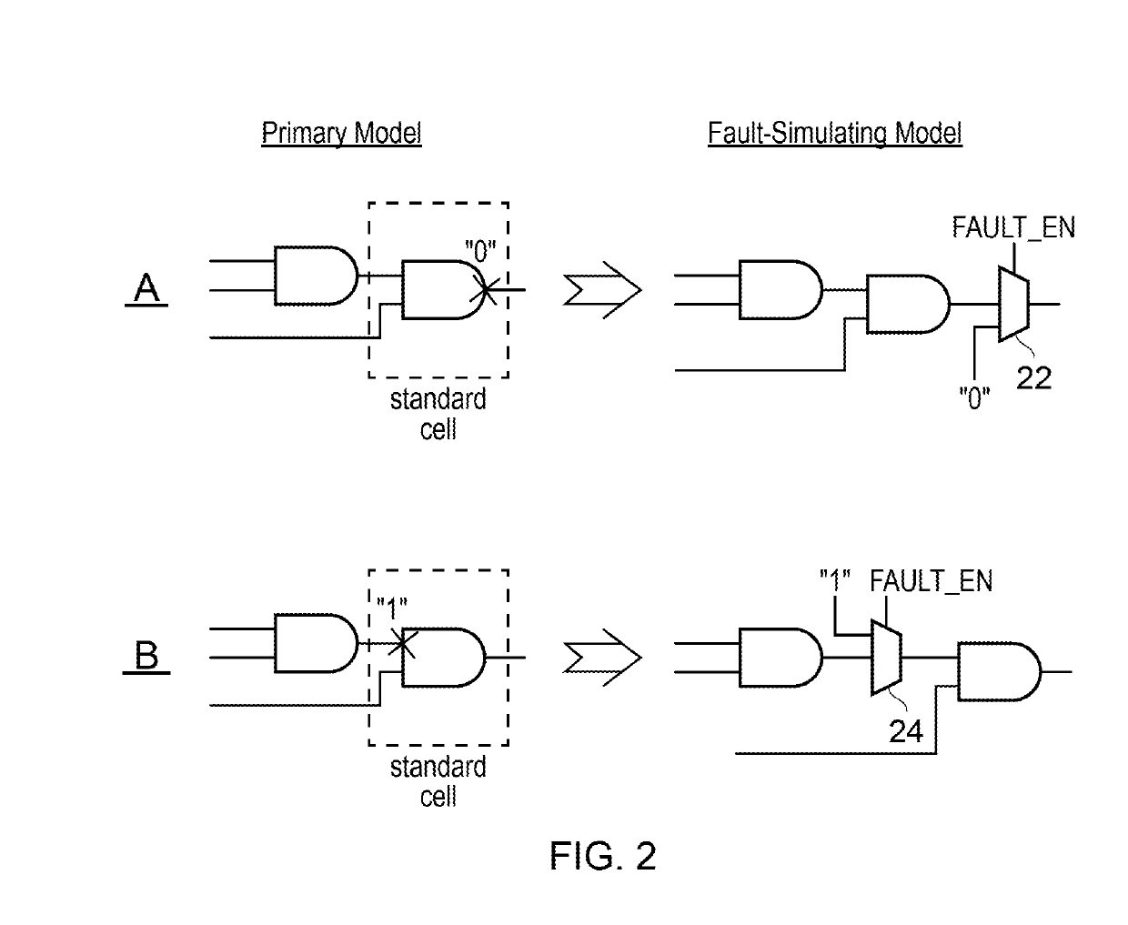
[0021 in FIG. 2 illustrates a further potential failure within the combination of the two AND gates. In this case one of the inputs to the final AND gate is subject to a stuck-at error tying it to a value of “1”. This failure can be simulated within the corresponding fault-simulating model by introducing a multiplexer 24 to selectively apply a fixed input value of “1” to the input of the final AND gate if this is selected by the FAULT_EN signal.

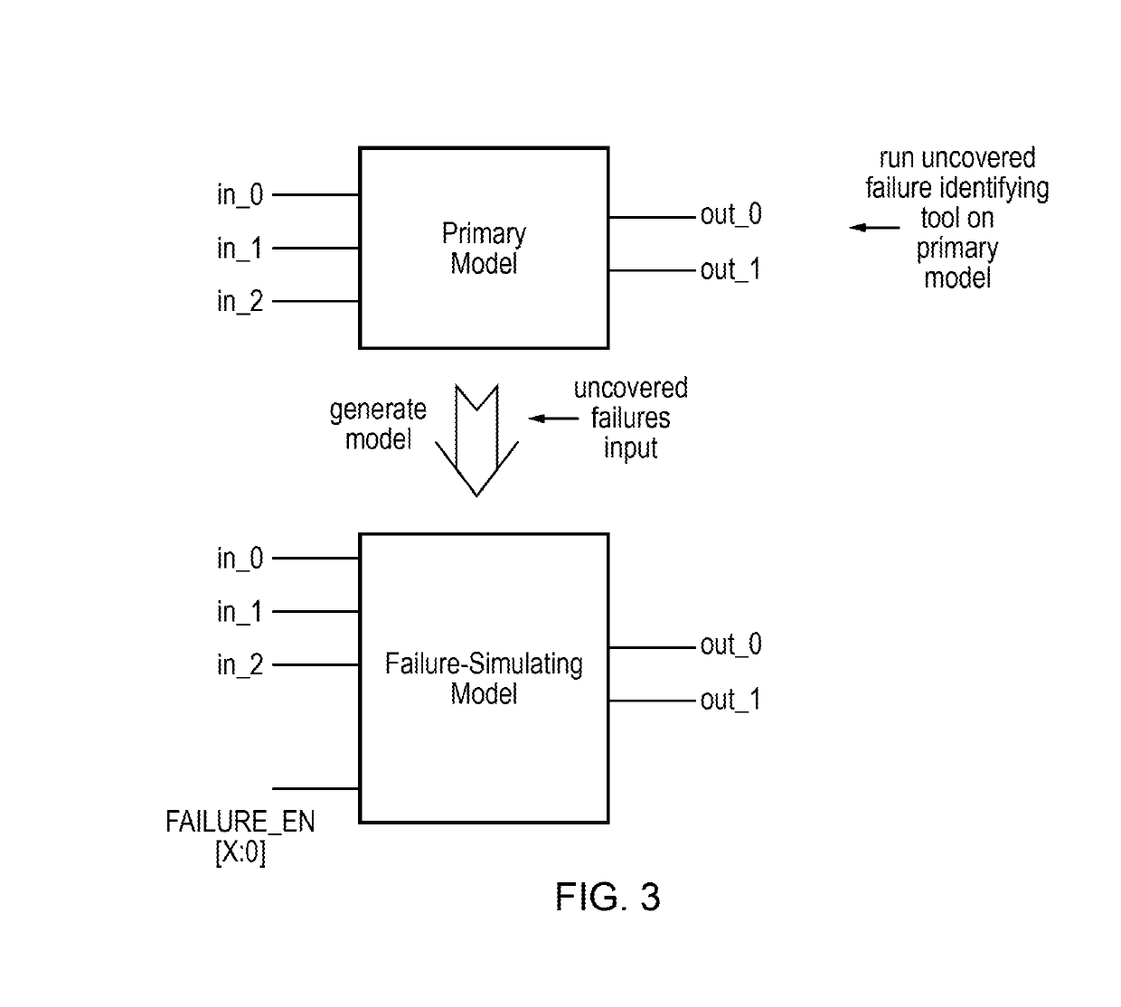
[0022]FIG. 3 schematically illustrates more generally how a failure-simulating model is related to a corresponding primary model of a portion of a target data processing apparatus. In this abstraction, the portion of the target data processing apparatus within which coverage of uncovered failures is to be improved is represented by a circuit block having three input signals and two output signals. It will be appreciated that in practice, such a portion of a target processing apparatus to be modelled may have many more inputs and outputs.

[0023...


PUM


Abstract

A simulation of software test program executing upon a primary model of a portion of a data processing apparatus is performed to identify uncovered (undetected) failures. A formal method analysis is then performed upon a combination of the primary model and a fault-simulating model simulating the uncovered failures in order to identify software stimuli that can render the uncovered failures detectable. The identified software stimuli are then added to the software test program to increase the failure coverage. The process is performed iteratively until a desired level of failure coverage is achieved.

Description

BACKGROUNDTechnical Field[0001]This disclosure relates to the field of data processing systems. More particularly, this disclosure relates to the generation of software test programs for detecting failures arising within data processing systems.Technical Background[0002]It is known that failures can arise during the life of data processing systems due to factors such as circuit ageing and particle strikes. In some circumstances the data processing systems concerned may be controlling safety critical operations and it is important that such failures are reliably detected. In order to assist in such detection, it is known to use software test programs which are regularly run by a target data processing system when in use. If the target data processing system is free from errors, then the result of running such a software test program will match the expected result. However, if there are failures within the target data processing system that change its response to executing program ins...

Claims


Application Information

Patent Timeline
IPC IPC(8): G06F11/36G06F8/65
CPCG06F11/3684G06F11/3608G06F11/368G06F8/65
Inventor LYBERIS, SPYROS
Owner ARM LTD
Learn More