Facilitating structural coverage of a design during design verification

a structural coverage and design technology, applied in the field of hardware design verification process, can solve the problems of design change and/or pollution, excessive manual process, and exposure to increase in verification complexity, and achieve the effect of facilitating verification

Active Publication Date: 2008-08-19
SYNOPSYS INC
View PDF4 Cites 6 Cited by
  • Summary
  • Abstract
  • Description
  • Claims
  • Application Information

AI Technical Summary

Benefits of technology

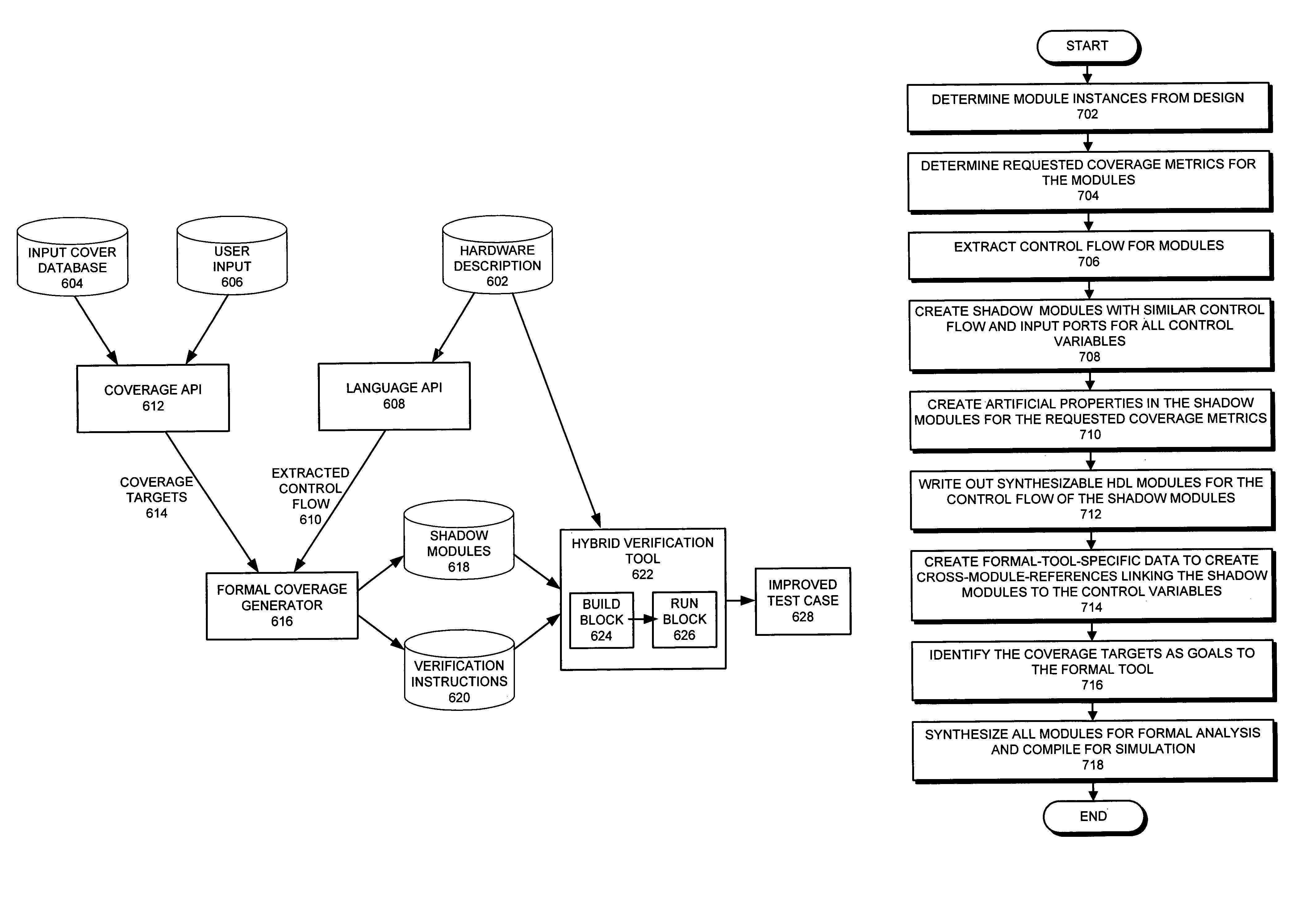
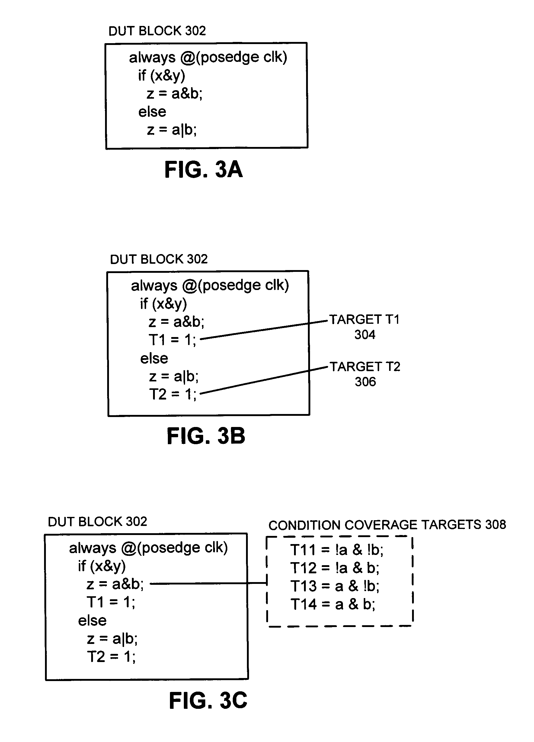
[0015]In a further variation, while generating the set of parallel structures within the shadow module, the system ensures that these parallel structures are language-correct. In doing so, the system replicates the control flow in the shadow module and the set of parallel structures to facilitate verification while preventing the hardware description from becoming changed and / or polluted.

Problems solved by technology

For instance, because of the non-linear nature of state machines, increasing the complexity of a design can lead to an exponential increase in the verification complexity.
However, despite increasing verification complexity, design correctness still must be verified to ensure that designs operate correctly.
While designers can build assertions and test cases to cover every aspect of the design, this manual process is extremely time-consuming.
While existing assertion-based verification techniques partially automate the verification process, they do so by modifying the hardware description to include assertions, which may cause design changes and / or pollution.
Furthermore, while an assertion violation proves that the design is not correct, proving design correctness is intractable, and there is no way to determine a “reasonable” testing timeframe that will flush out most of the design bugs.
An additional limitation is that current coverage techniques are implemented using simulation techniques that do not leverage the formal verification techniques typically employed for model checking.

Method used


Image

  • Facilitating structural coverage of a design during design verification
  • Facilitating structural coverage of a design during design verification
  • Facilitating structural coverage of a design during design verification

Examples


Embodiment Construction

[0026]The following description is presented to enable any person skilled in the art to make and use the invention, and is provided in the context of a particular application and its requirements. Various modifications to the disclosed embodiments will be readily apparent to those skilled in the art, and the general principles defined herein may be applied to other embodiments and applications without departing from the spirit and scope of the present invention. Thus, the present invention is not limited to the embodiments shown, but is to be accorded the widest scope consistent with the principles and features disclosed herein.

[0027]The data structures and code described in this detailed description are typically stored on a computer-readable storage medium, which may be any device or medium that can store code and / or data for use by a computer system. This includes, but is not limited to, magnetic and optical storage devices such as disk drives, magnetic tape, CDs (compact discs) ...


PUM


Abstract

One embodiment of the present invention provides a method and a system that facilitates structural coverage of a design during a design verification process. During operation, the system receives a hardware description of the design, which contains one or more module instances and a set of structural coverage targets for a set of structures in the design. The system then extracts a control flow, the set of structural coverage targets, and a set of structural coverage metrics for the hardware description, and creates a shadow module with the same control flow as the hardware description. This shadow module contains a set of parallel structures that correspond to the set of structural coverage targets in the control flow of the hardware description and serve as targets for formal methods used to analyze the design. The system also generates a set of cross-module references to link the set of parallel structures in the shadow module with signals from the set of structures in the hardware description. The system then applies a formal verification tool to the design, including the shadow module and the cross-module references in an attempt to achieve the desired structural coverage.

Description

BACKGROUND[0001]1. Field of the Invention[0002]The present invention relates to the process of verifying a hardware design to ensure that it operates correctly. More specifically, the present invention relates to a method and an apparatus for facilitating structural coverage of a design during a design verification process.[0003]2. Related Art[0004]Verification techniques which are presently used to ensure the functional correctness of integrated circuits do not scale with the complexity of circuit designs. For instance, because of the non-linear nature of state machines, increasing the complexity of a design can lead to an exponential increase in the verification complexity. For example, each additional state element in a state machine doubles the size of the state-space to be verified. However, despite increasing verification complexity, design correctness still must be verified to ensure that designs operate correctly.[0005]Design verification techniques attempt to determine whet...

Claims


Application Information

Patent Timeline
Patent Type & Authority Patents(United States)
IPC IPC(8): G06F17/50
CPCG06F17/504G06F17/5022G06F30/33G06F30/3323
Inventor HARER, KEVIN M.MUNISHWAR, MANDAR
Owner SYNOPSYS INC
Why Eureka
Try Eureka