Robot control system, robot system, and sensor information processing apparatus

Active Publication Date: 2013-05-09
SEIKO EPSON CORP
View PDF8 Cites 78 Cited by
  • Summary
  • Abstract
  • Description
  • Claims
  • Application Information

AI Technical Summary

Benefits of technology

[0010]An advantage of some aspects of the invention is to provide a robot control system, a robot system, a sensor information proc

Problems solved by technology

Patent Literature 2 discloses a method of providing a motion model on the inside of a control system to thereby, estimate force and performing the impedance control while making it unnecessary to use a sensor, although the control system

Method used


Image

  • Robot control system, robot system, and sensor information processing apparatus
  • Robot control system, robot system, and sensor information processing apparatus
  • Robot control system, robot system, and sensor information processing apparatus

Examples


first embodiment

2. First Embodiment

2.1 Configuration

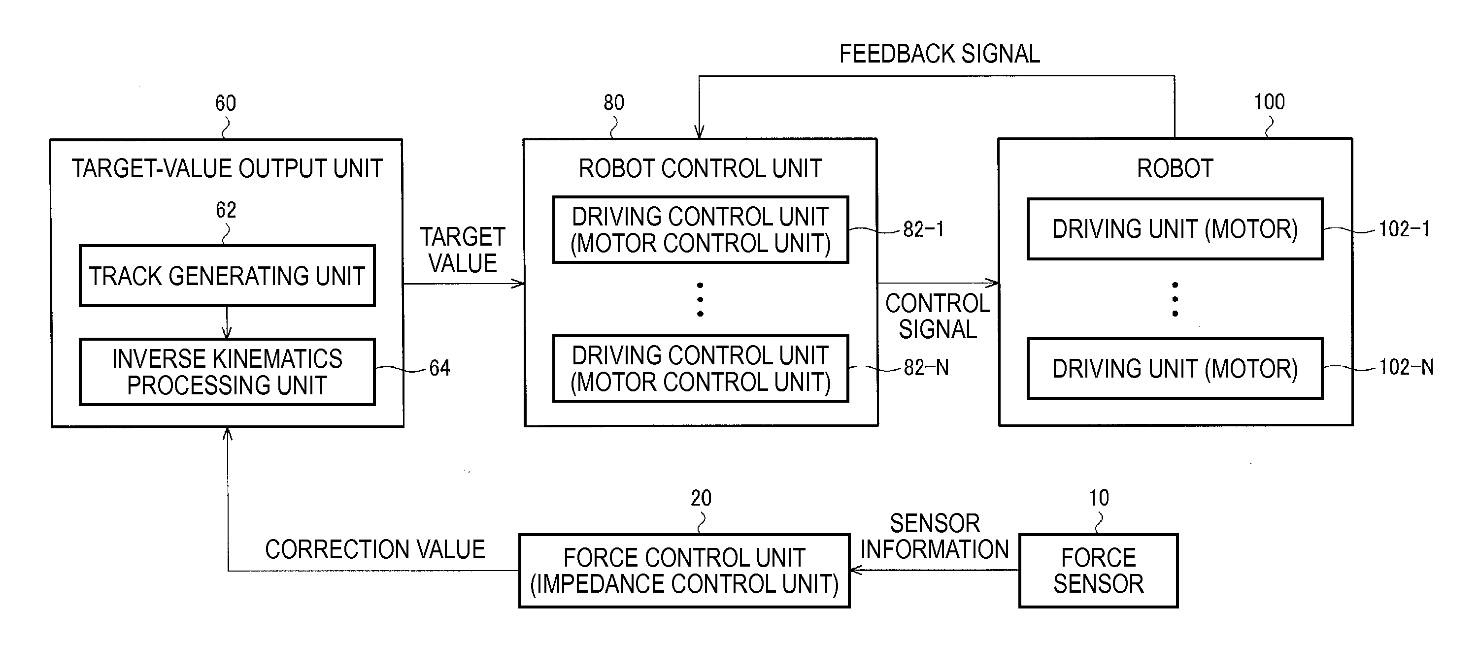
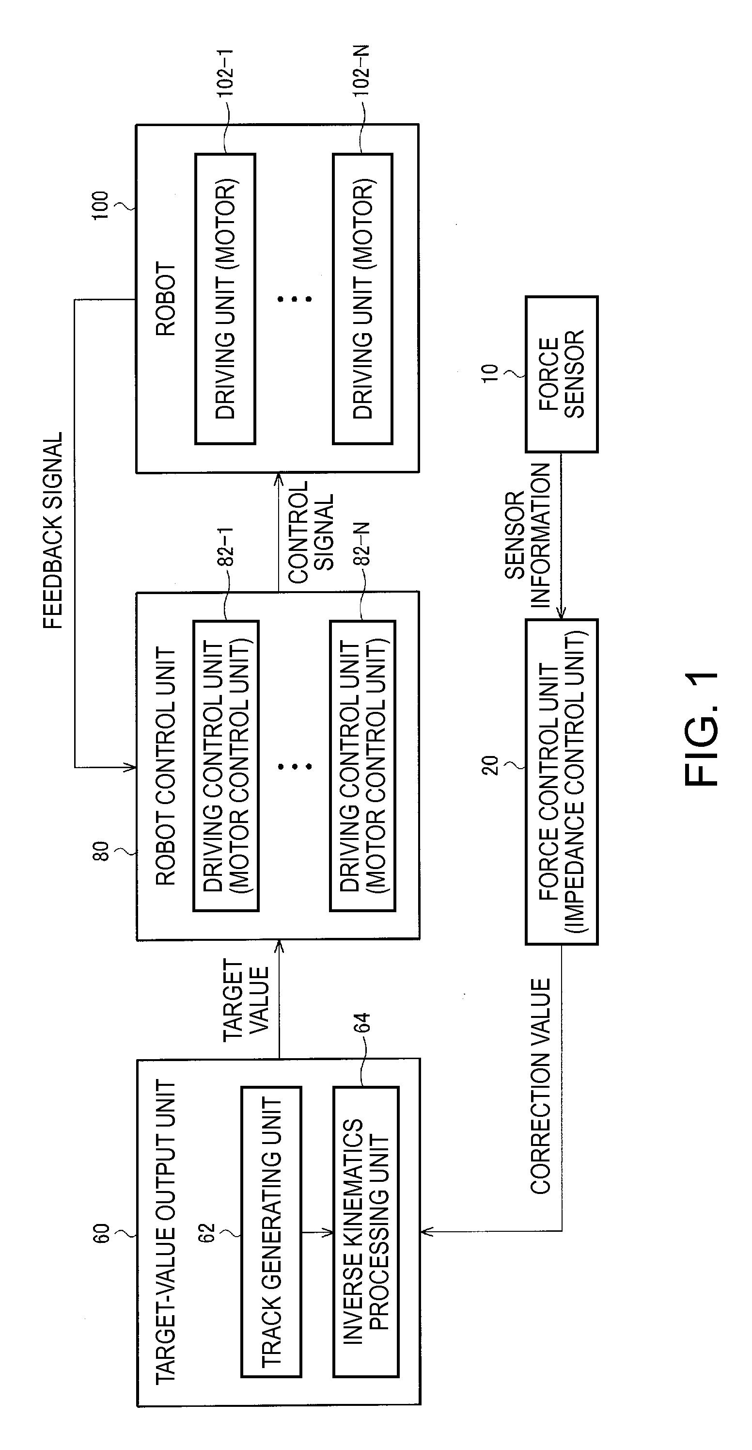
[0111]A configuration example of a robot system including a robot control system according to the first embodiment is shown in FIG. 11.

[0112]Since the force sensor 10, the track generating unit 62, the inverse kinematics processing unit 64, the motor control unit 82-1, and the like are the same as those shown in FIG. 1. Therefore, detailed explanation thereof is omitted. An input correcting unit 30 applies correction processing to sensor information. For example, the input correcting unit 30 may include, for example, the posture correcting unit 532 and the hand-tool-own-weight correcting unit 534 shown in FIG. 7. A forward kinematics processing unit 40 corresponds to the forward kinematics processing unit 540 shown in FIG. 7. The forward kinematics processing unit 40 outputs a result of forward kinematics processing to the input correcting unit 30 and outputs the result to the track generating unit 62 as well according to necessity.

[0113]The robot...

second embodiment

3. Second Embodiment

[0146]In a second embodiment, it is assumed that a driving frequency of a digital filter is switched. For example, it is conceivable to switch the driving frequency according to band limitation. In general, noise is often included in sensor information of a force sensor. Therefore, it is desirable to perform band limiting processing. However, the width of a pass band varies depending on a situation (if a large signal value is obtained with respect to noise, the band limiting processing may be rather light and the pass band can be set wide). As the pass band is set narrower, the noise further decreases but a response characteristic is further deteriorated. Therefore, it is necessary to switch the driving frequency of the digital filter as well to correspond to the pass band. Specifically, when the pass band is set wide, the digital filter is caused to operate at a high driving frequency and, when the pass band is set narrow, the digital filter is caused to operate...

third embodiment

4. Third Embodiment

[0167]In a third embodiment, as in the second embodiment, it is assumed that a driving frequency of a digital filter is switched. In this embodiment, a configuration including only one digital filter arithmetic unit 221 that performs digital filter processing is explained. When only one digital filter arithmetic unit 221 is provided, it is necessary to perform switching processing when the driving frequency is switched. Specifically, as the switching processing, switching from a high frequency to a low frequency and switching from a low frequency to a high frequency are separately explained.

4.1 Configuration

[0168]A configuration example of a robot system including a robot control system according to the third embodiment is shown in FIG. 15. Detailed explanation of components same as those in the second embodiment (FIG. 13) is omitted. When compared with the second embodiment, the third embodiment is different in that only one digital filter arithmetic unit 221 is ...


PUM


Abstract

A robot control system includes a force control unit configured to output a correction value of a target track of a robot on the basis of sensor information acquired from a force sensor, a target-value output unit configured to apply correction processing based on the correction value to the target track to calculate a target value and output the calculated target value, and a robot control unit configured to perform feedback control of the robot on the basis of the target value. The force control unit includes a digital filter unit. The force control unit applies digital filter processing by the digital filter unit to the sensor information to calculate a solution of an ordinary differential equation in force control and outputs the correction value on the basis of the calculated solution.

Description

BACKGROUND[0001]1. Technical Field[0002]The present invention relates to a robot control system, a robot system, a sensor information processing apparatus, and the like.[0003]2. Related Art[0004]As work performed using a robot such as a manipulator, there is work involving various constraint conditions such as contact with an object. In such a case, in addition to position control, force control is often required. For example, when the surface of an object is traced, when one object is fitted in another object, or when a soft object is gripped not to be broken, a motion corresponding to reaction from the object is necessary in addition to simple position control.[0005]As a representative method for performing force control in a robot, there is a method called impedance control. The impedance control is a control method for causing a robot to act, irrespective of the actual mass, the viscosity characteristic, and the elasticity characteristic of the robot, as if the robot has values ...

Claims


Application Information

Patent Timeline
IPC IPC(8): G05B19/042
CPCB25J9/16B25J13/08B25J9/1633G05B2219/41166G05B2219/39343G05B2219/39529G05B2219/39325Y10S901/09B25J9/1612B25J9/1694
Inventor INAZUMI, MITSUHIRO
Owner SEIKO EPSON CORP
Why Eureka
Try Eureka