
Hydraulic damper with a hydraulic compression stop assembly

a technology of hydraulic stop and damper, which is applied in the direction of shock absorbers, springs/dampers functional characteristics, transportation and packaging, etc., can solve the problems of damage to the internal components of dampers, rapid increase of forces, etc., and achieve the effect of efficient and simple manufacture and assembly

Active Publication Date: 2019-06-20
BEIJING WEST IND CO LTD
View PDF5 Cites 6 Cited by
  • Summary
  • Abstract
  • Description
  • Claims
  • Application Information

AI Technical Summary

Benefits of technology

The present invention provides a hydraulic damper with a hydraulic compression stop assembly that is efficient, easy to make and assemble, and limits the maximum damping force generated by the assembly.

Problems solved by technology

Although hydraulic compression stop assemblies of this kind provide versatile tuning opportunities for shaping damping force characteristics at the very high velocities that may occur during the compression stroke (e.g., while a vehicle hits an obstacle), forces can increase rapidly leading even to damage of the internal components of the damper.

Method used


Image

  • Hydraulic damper with a hydraulic compression stop assembly
  • Hydraulic damper with a hydraulic compression stop assembly
  • Hydraulic damper with a hydraulic compression stop assembly

Examples


Embodiment Construction

[0025]Referring to the Figures, wherein like numerals indicate corresponding parts throughout the several views,

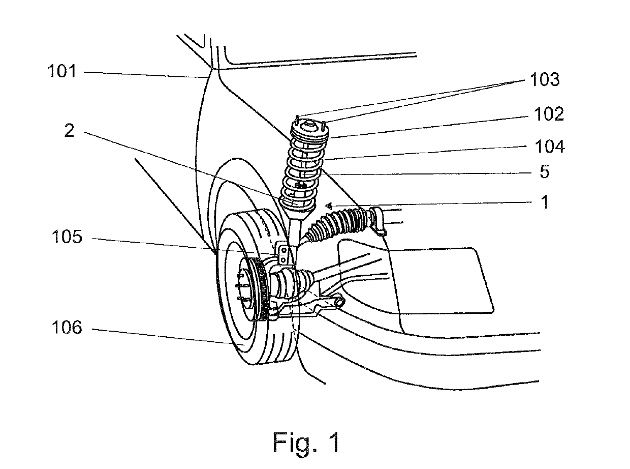
[0026]FIG. 1 schematically illustrates a fragment of an exemplary vehicle suspension comprising the damper 1 of the present invention attached to a vehicle chassis 101 by means of a top mount 102 and a number of screws 103 disposed on the periphery of an upper surface of the top mount 102. The top mount 102 is connected to a coil spring 104 and a piston rod 5 of the damper 1. The tube 2 of the damper 1 is connected to a steering knuckle 105 supporting a vehicle wheel 106.

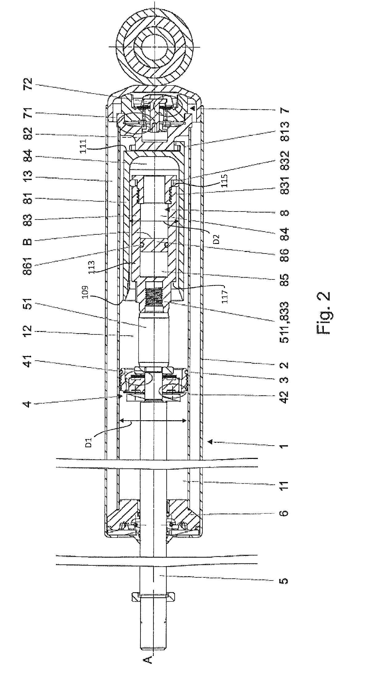
[0027]FIG. 2 presents an embodiment of a twin-tube damper 1 according to the present invention. The damper 1 comprises an external tube 2 and a main tube 3, each extending about and along an axis A and filled with viscous working liquid inside of which a movable piston assembly 4 attached to a piston rod 5 led outside the damper 1 through a sealed piston rod guide 6 is disposed. The main tube 3 has a first...


PUM


Abstract

A hydraulic damper for a vehicle including a main tube. A first piston assembly is slideably disposed in the main tube and axially divides the main tube into a rebound chamber and a primary compression chamber. A hydraulic compression stop assembly is disposed in the primary compression chamber and includes a narrowed section extending between an open end and a closed end. A second piston assembly is slideably disposed in the narrowed section and is coupled with the first piston assembly. The second piston assembly has a piston tube that extends between an opened end and a shut end. A displaceable partition is slideably disposed in the piston tube. A first auxiliary compression chamber is defined between the partition and the closed end of the narrowed section. A second auxiliary compression chamber is defined between the partition and the shut end of the piston tube.

Description

TECHNICAL FIELD[0001]The present invention generally relates to a hydraulic damper for a vehicle. More particularly, the present invention relates to a hydraulic damper including a hydraulic compression stop assembly.BACKGROUND OF THE INVENTION[0002]It is known in the art for hydraulic dampers to include a hydraulic compression stop assembly for generating an additional damping force over a predefined section of the piston rod travel during a compression stroke.[0003]An example of such a hydraulic damper is disclosed in international patent application publication no. WO2016146660 which discloses a hydraulic stop member comprising a cup-shaped body, which is adapted to be mounted in a compression chamber. The cup-shaped body is open at its top end facing towards the piston of the shock-absorber, and comprises a side wall and a bottom wall which define, along with the plunger, a working chamber. The side wall and the bottom wall are made as separate pieces and are connected to each o...

Claims


Application Information

Patent Timeline
Patent Type & Authority Applications(United States)
IPC IPC(8): F16F9/516F16F13/00F16F9/16F16F9/346F16F9/49B60G13/08B60G15/06B60G17/08
CPCF16F9/516F16F13/007F16F9/165F16F9/3465F16F9/49B60G13/08B60G15/061B60G17/08B60G2500/10B60G2202/24B60G2800/162B60G2206/41F16F2228/066F16F2230/42F16F9/26F16F9/3214F16F9/34F16F2222/12F16F9/3405
Inventor FLACHT, PIOTR ANDRZEJ
Owner BEIJING WEST IND CO LTD
Learn More