
Rotor-rotor shaft-assembly with material matched connection

A rotor shaft and rotor technology, applied in the direction of electric components, magnetic circuit rotating parts, electrical components, etc., can solve the problems of impractical assembly, reduced torque transmission, difficult assembly, etc., and achieve cost-effective and reliable torque transmission. Effect

Inactive Publication Date: 2019-10-08
VOLKSWAGEN AG
View PDF9 Cites 0 Cited by
  • Summary
  • Abstract
  • Description
  • Claims
  • Application Information

AI Technical Summary

Problems solved by technology

In order to counteract this effect, the cover has to be raised significantly, which however makes assembly considerably more difficult or possibly even impossible
To assemble a groove and tenon joint it must be designed with a certain amount of play, which however can lead to reduced torque transmission and thus power loss and unpleasant acoustic effects

Method used


Image

  • Rotor-rotor shaft-assembly with material matched connection
  • Rotor-rotor shaft-assembly with material matched connection
  • Rotor-rotor shaft-assembly with material matched connection

Examples


Embodiment Construction

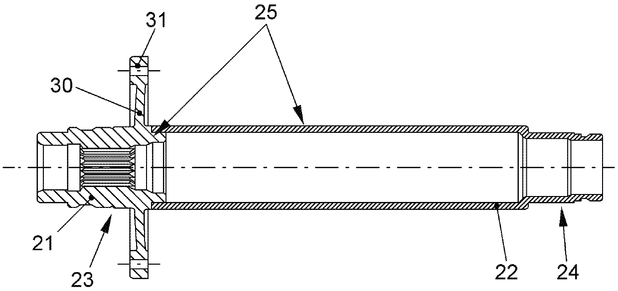
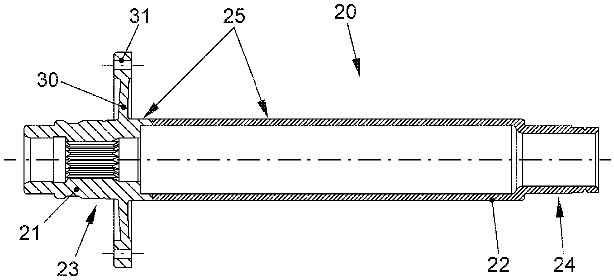
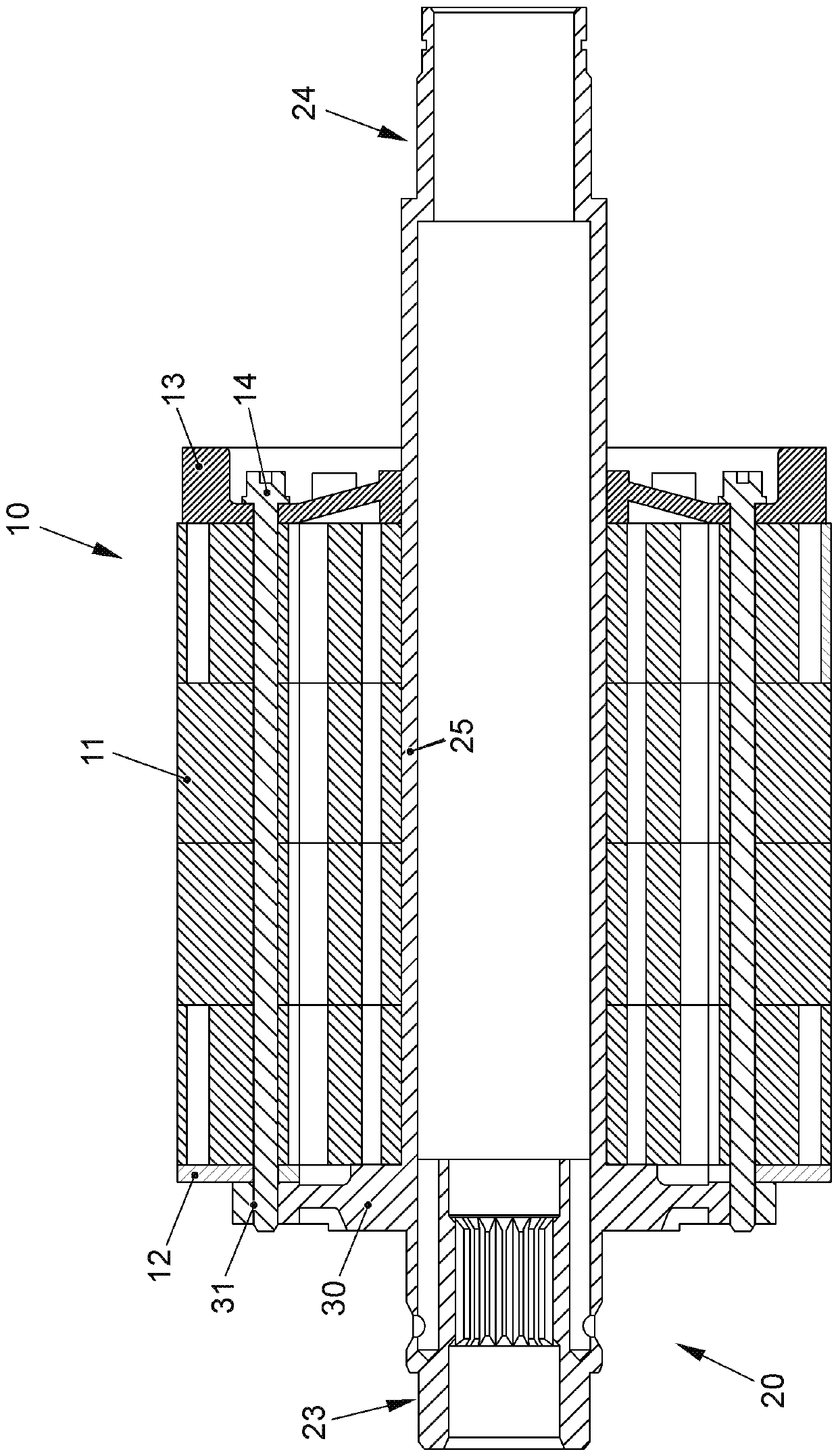
[0037] figure 1 and 2 show an embodiment of a rotor-rotor shaft assembly according to the invention for an electric machine, for example for a motor vehicle, for example for an electric vehicle and / or a hybrid vehicle.

[0038] figure 1 2 and 2 show that the rotor-rotor shaft assembly has a rotor 10 , a rotor shaft 20 and a rotor flange 30 for fastening the rotor 10 on the rotor shaft 20 . In this case, a material-fit connection is formed between the rotor shaft 20 and the rotor flange 30 , that is to say the rotor flange 30 is formed in one piece with a part of the rotor shaft.

[0039] The rotor 10 here has a plurality of rotor laminations 11 and a spacer disk 12 arranged between the rotor laminations 11 and the rotor flange 30 , in particular for magnetically decoupling the rotor laminations 11 from the rotor flange 30 . The rotor 10 also has tensioning and / or balancing discs 13 and tensioning screws 14 . Here, the spacer disk 12 and the rotor disk pack 11 are arranged bet...


PUM


Abstract

The invention relates to a rotor-rotor shaft-assembly with material matched connection, and specifically relates to a rotor-rotor shaft-assembly, which is especially suitable for a motor and has a rotor (10) and a rotor shaft (20). Between the rotor shaft (20) and a rotor flange (30), in order to fix the rotor (10) on the rotor shaft (20), material matched connection is arranged. The rotor shaft (20) extends and penetrates the rotor (10), and support segments (23,24) for rotatingly support the rotor (10) are formed on two sides of the rotor (10). The rotor-rotor shaft-assembly can be simply manufactured, the cost is proper, and / or the manufacturing process is reliable. Reliable torque transmission can be guaranteed, even if the rotation speed is large such as 16000 l / min.

Description

technical field [0001] The invention relates to a rotor-rotor shaft assembly, eg for an electric machine of a motor vehicle, eg an electric vehicle and / or a hybrid vehicle, according to the features of the preamble of patent claim 1 . Background technique [0002] There are different possibilities for torque transmission from, in particular, the rotor of the electric machine to the rotor shaft. For example, by means of a press bond with a large covering between the rotor lamella and the rotor shaft or by a plurality of, for example four or five, distributed over the circumference between the rotor lamella and the rotor shaft Groove and tenon connection for torque transmission. [0003] A rotor-rotor shaft assembly for an electric machine is known from DE 10 2011 012 429 A1, in which the rotor shaft is constructed in multiple parts from two side covers and a base body arranged between the side covers. In one embodiment, the side cover is connected to the base body by means ...

Claims


Application Information

Patent Timeline
IPC IPC(8): H02K1/28H02K7/04H02K7/00
CPCH02K1/28H02K7/003H02K7/04H02K1/30H02K1/32H02K15/165
Inventor M.埃施托夫F.魏卡德
Owner VOLKSWAGEN AG
Learn More