
Hydraulic damper with a hydraulic stop arrangement

a technology of hydraulic stop and damper, which is applied in the direction of spring/damper functional characteristics, shock absorbers, transportation and packaging, etc., can solve the problems of failure of the entire damper during benchmark tests, and achieve the effects of increasing damping force, cost saving and simple manufacturing, and robust and reliabl

Active Publication Date: 2020-03-31
BEIJING WEST IND CO LTD
View PDF31 Cites 4 Cited by
  • Summary
  • Abstract
  • Description
  • Claims
  • Application Information

AI Technical Summary

Benefits of technology

The present invention is a damper assembly with a progressive and adjustable piston that increases the damping force in response to rod displacement. This results in a more robust and reliable assembly that is cost-effective and easy to manufacture. Additionally, the hydraulic stop arrangement can be added onto existing damper constructions. This invention also reduces hydraulic imbalance and minimizes the impact of misaligned sealing rings, preventing them from extruding into the space between the main tube and the upper member. The sealing ring of the additional piston has increased stiffness to improve its durability.

Problems solved by technology

Unfortunately these requirements are contradicting and thus the sealing ring expanding radially under pressure of the working liquid is prone to be extruded or squeezed into to a space between the narrowed section of the tube and the additional piston assembly.
The inventors observed such an undesirable effect that resulted in failure of the entire damper during benchmark tests.

Method used


Image

  • Hydraulic damper with a hydraulic stop arrangement
  • Hydraulic damper with a hydraulic stop arrangement
  • Hydraulic damper with a hydraulic stop arrangement

Examples


Embodiment Construction

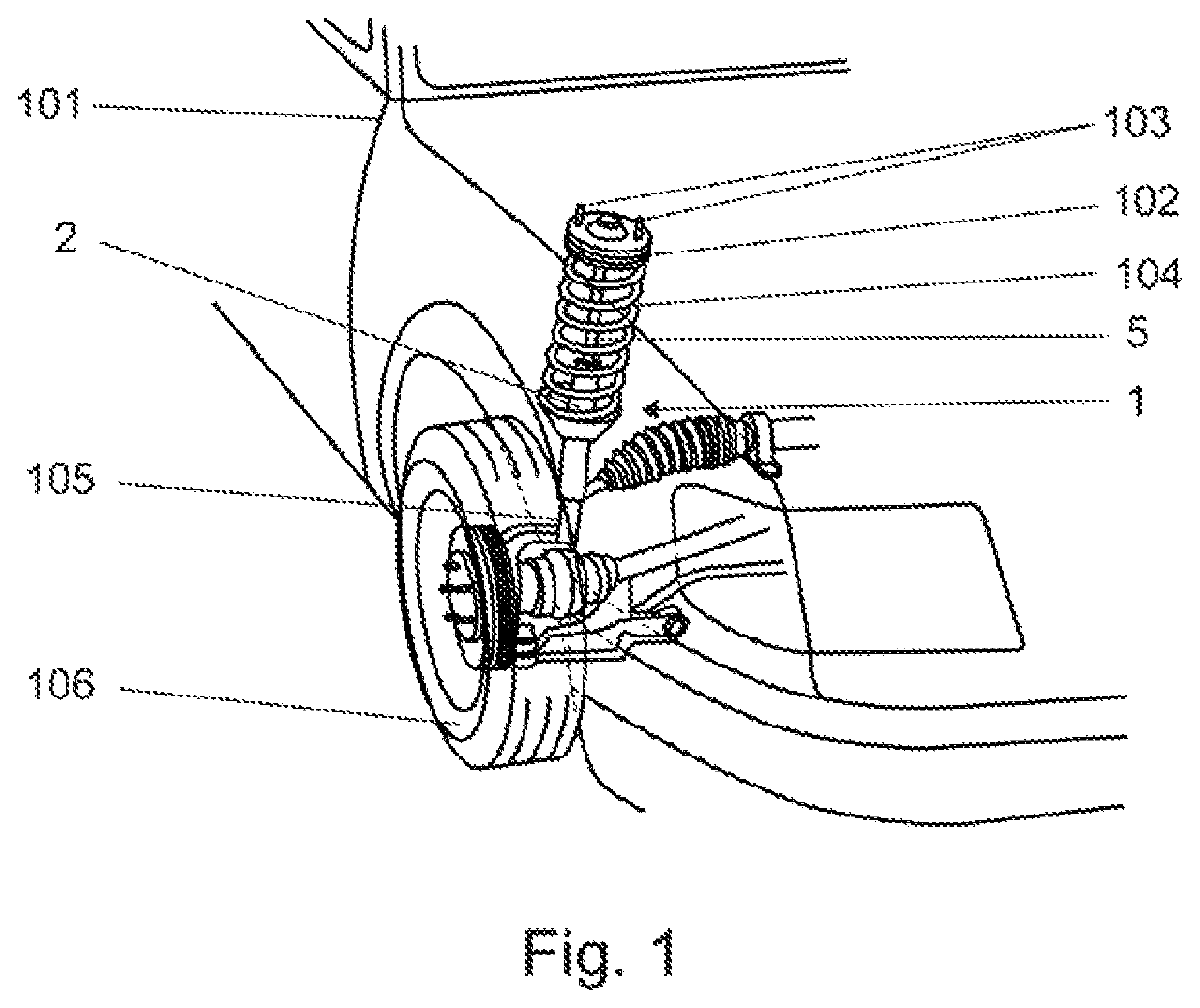
[0015]Referring to the Figures, wherein like numerals indicate corresponding parts throughout the several views, it is one aspect of the present invention to provide a damper assembly 1 for a vehicle. A generally illustrated in FIG. 1, the damper assembly 1 is attached to a vehicle chassis 101 by a top mount 102. A number of screws 103 is disposed on the periphery of the upper surface of the top mount 102 to fasten the top mount 102 to the vehicle chassis 101. The top mount 102 is connected to a coil spring 104 and a piston rod 5 of the damper assembly 1. The damper assembly 1 is also connected to the knuckle 105 supporting the vehicle wheel 106.

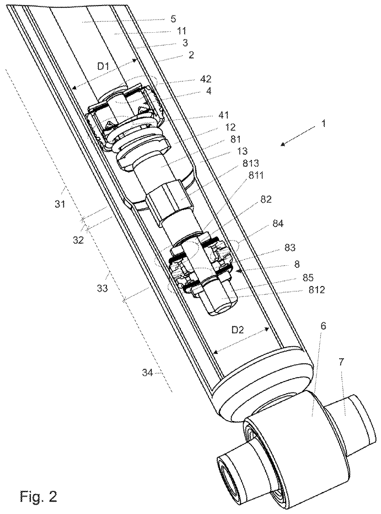
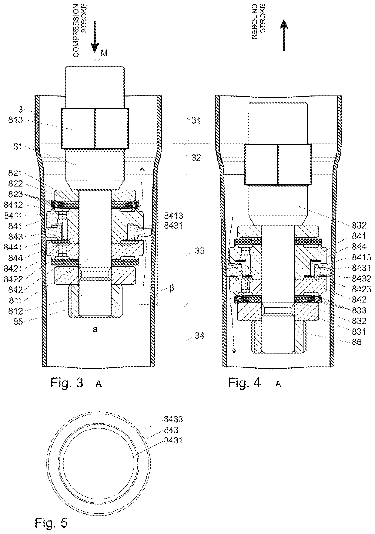
[0016]The damper assembly 1 includes a main tube 3, having a generally cylindrical shape, disposed on a center axis A between a first end and second end. The damper assembly 1 defines a fluid chamber 11, 12 extending along the center axis A between the first end and the second end for containing a working fluid. An external tube 2, having a ...


PUM

PropertyMeasurementUnit
angleaaaaaaaaaa
diameter D1aaaaaaaaaa

Abstract

A damper assembly includes a main tube disposed on a center axis and defines a fluid chamber for containing a working fluid. A main piston is disposed in the fluid chamber dividing the fluid chamber into a rebound and a compression chamber. A piston rod is attached to the main piston for moving the main piston between a compression stroke and a rebound stroke. An additional piston is attached to the piston rod adjacent to the main piston. The additional piston includes a body having an upper and a lower member defining a groove. A sealing ring is disposed in the groove and being radially expandable in response to a working fluid pressure. The sealing ring includes at least one annular collar extending outwardly from the sealing ring for forming a locking engagement with the upper and lower members to limit the radial expansion of the sealing ring.

Description

CROSS REFERENCE TO RELATED APPLICATION[0001]This application claims the benefit of U.S. Provisional Patent Application Ser. No. 62 / 662,203 filed on Apr. 24, 2018, the entire disclosure of which is incorporated herein by reference in its entirety.BACKGROUND OF THE INVENTION1. Field of the Invention[0002]The present invention generally relates to a damper assembly for a vehicle.2. Description of the Prior Art[0003]Damper assemblies are well known in the art for use in a vehicle. One such a damper assembly is disclosed in patent publications EP 2 302 252 or EP 2 952 775. The damper assembly includes a hydraulic stop arrangement which provides progressive generation of additional damping force depending not only on the additional piston position but also on its velocity, which may be tunable to a large extent.[0004]U.S. Provisional Patent application US 62 / 456,283 discloses a damper assembly including a main tube disposed on a center axis and extending between a first end and a second e...

Claims


Application Information

Patent Timeline
Patent Type & Authority Patents(United States)
IPC IPC(8): F16F9/49B60G17/08F16F9/48F16F9/36B60G13/08F16F9/18F16F9/32F16F9/348
CPCF16F9/49F16F9/368B60G13/08F16F9/483F16F9/3214F16F9/3221F16F9/3235F16F9/185B60G17/08F16F2228/066F16F2224/0291B60G2800/162F16F2228/14B60G2202/24F16F9/348B60G2206/7104B60G2500/10B60G2206/41F16F2222/12F16J15/3224
Inventor KASPRZYK, DOMINIKMATON, PIOTR GRZEGORZKUS, PAWEL EDWARD
Owner BEIJING WEST IND CO LTD
Learn More