Touch and stylus sensing

Inactive Publication Date: 2019-06-20
AZOTEQ PTY LTD
View PDF3 Cites 6 Cited by
  • Summary
  • Abstract
  • Description
  • Claims
  • Application Information

AI Technical Summary

Benefits of technology

[0040]As described earlier in the present disclosure, a resonant transmitter coil or coils may be used together with a plurality of resonant receiver coils to detect the position of a passive stylus which comprise a magnetic member point, for example a ferrite point, with each coil connected to a resonant capacitor, said capacitor chosen to achieve a theoretical first resonant frequency. However, it has been observed in practice that for the usage case where all coils are allowed to resonate simultaneously, i.e. all coils have their capacitors connected and the transmitter coil is driven at said first resonant frequency, resonances at multiple frequencies occur, which may significantly increase the amount of effort required to translate receiver inductance measurements into stylus position. The present inventors have found that by lowering the frequency of the drive signal connected to the transmitter coil or coils to slightly below the theoretical first resonant frequency, a stable situation results, where the position of a ferrite tipped passive stylus may be discerned without undue effort. To clarify, the present invention teaches use of a single or a plurality of transmitter coils, with each transmitter coil connected to a resonant capacitor calculated to result in a first theoretical resonant frequency, and use of a plurality of receiver coils coupled to said transmitter coil or coils to detect the position of a passive, ferrite tipped stylus, wherein each receiver coil is connected to a resonant capacitor calculated to result in said first resonant frequency, but wherein said transmitter coil or coils is driven at a frequency somewhat lower or higher than said first resonant frequency, thereby reducing the detrimental impact of multiple resonant points while still utilizing increased gain. This may allow accurate stylus position detection while still utilizing energy storag

Problems solved by technology

However, if a user applies more than a specific amount of force to said magnetic or flexible members, the flexible member may suddenly deflect downwards, also known as snapping through.
When less than sai

Method used


Image

  • Touch and stylus sensing
  • Touch and stylus sensing
  • Touch and stylus sensing

Examples


Example

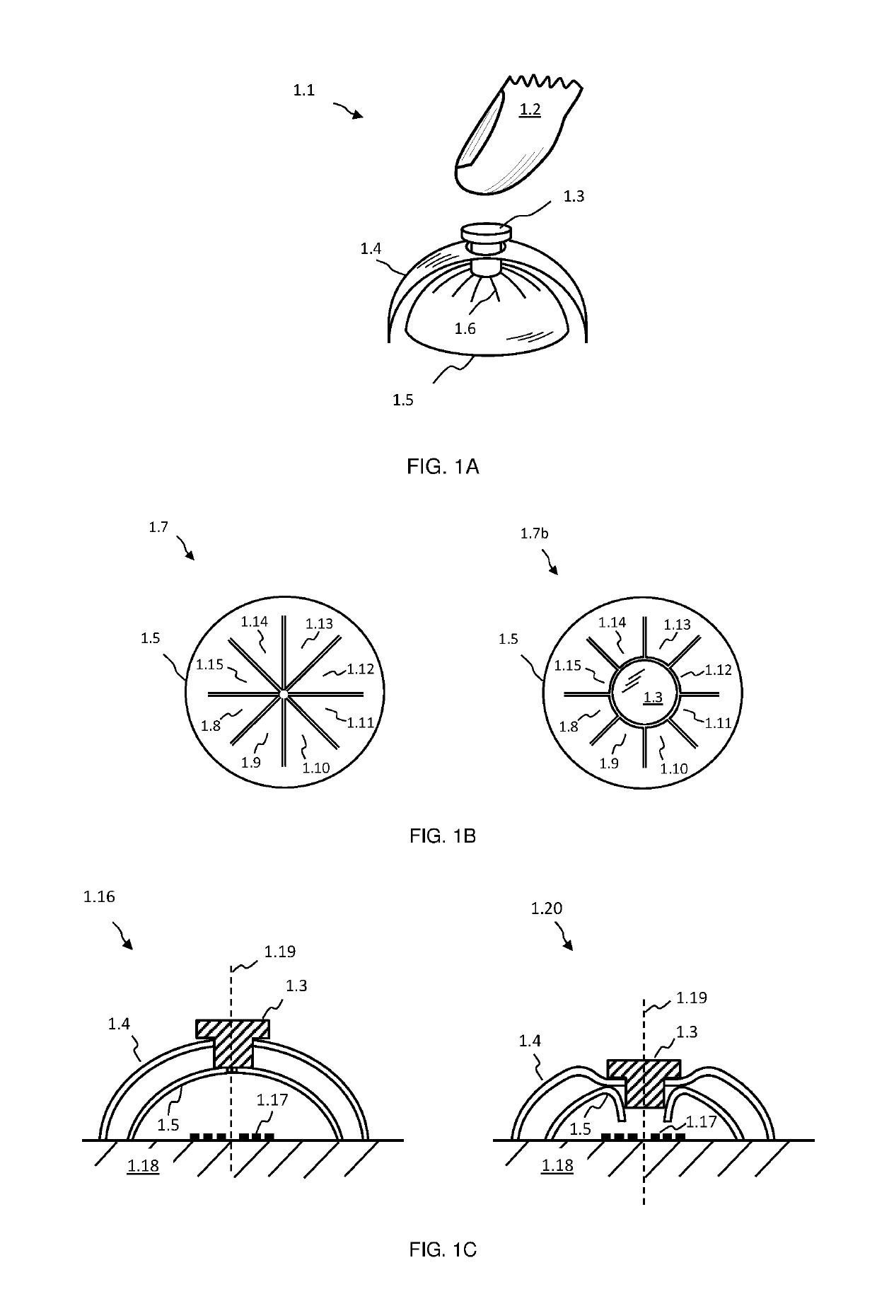
[0093]In FIG. 1A an exemplary inductive sensing based push button embodiment of the present invention is depicted at 1.1. A users finger 1.2, or another engaging object or device, may apply pressure or force to a magnetic member, for example a ferrite member, 1.3, or to material attached to member 1.3. The latter may be supported and held in place by a flexible member 1.4, which may be resilient in nature and deflect downwards when pressed. If sufficient force or pressure is applied to member 1.3, or to material attached to it, and thereby to flexible member 1.4, the latter may suddenly give way and substantially deflect downwards, known as snapping through. Members 1.3 and 1.4 are located over a conductive dome structure 1.5, which in turn is located over a coil or inductive structure (not shown), wherein said coil may experience eddy current losses due to dome 1.5, which may result in a decreased inductance measured by an inductive sensing circuit (not shown), for example a charge...


PUM


Abstract

A trackpad for a dual user interface has capacitive sensing and inductive sensing capabilities, charge transfer measurement circuitry, a set of a plurality of sensing electrode structures, a set of a plurality of inductive receiving coils and at least one inductive transmit coil. The set of sensing electrode structures is used with the charge transfer measurement circuitry for capacitive sensing and the capacitive sensing is used to discern user input via finger proximity or touch. The set of inductive receiving coils is used with the charge transfer measurement circuitry for inductive sensing and the inductive sensing is used to discern user input via a stylus.

Description

CROSS-REFERENCE TO RELATED APPLICATION[0001]The present application claims priority from South Africa application ZA 2017 / 08524, filed on Dec. 15, 2017, and South Africa application ZA 2018 / 03620, filed on May 31, 2018, the contents of which are hereby incorporated by reference into this application.BACKGROUND OF THE INVENTION[0002]Inductive sensing buttons which utilize conductive or magnetic material to influence the inductance of a measured structure are known in the art. For example, in U.S. Pat. No. 8,847,892 laminar structures which use either a bulk conductor or magnetic material being pushed closer to a sensing coil are disclosed. In US 2011 / 0187284 inductive sensing buttons with a metal target located below an outer surface are taught, wherein the outer surface is depressed by a user, causing the metal target to be pushed towards a sensing coil.[0003]When a metal target is pressed closer to an inductive coil structure, the inductance of the structure typically decreases due...

Claims


Application Information

Patent Timeline
IPC IPC(8): G06F3/041G06F3/044G06F3/046G06F3/0354G06F3/038G06F3/0488G06F3/14
CPCG06F3/0416G06F3/044G06F3/046G06F3/03545G06F3/03547G06F3/038G06F3/04883G06F3/1423G06F2203/04108G06F2203/04106G06F2203/04104G06F3/1462G09G2354/00G09G2370/06
Inventor BRUWERBRAND, TOBIAS GERHARDUSVAN WYK, JACOBUS DANIEL
Owner AZOTEQ PTY LTD
Why Eureka
Try Eureka