Detector array and a spectrometer system

Pending Publication Date: 2022-11-10
TRINAMIX GMBH
View PDF0 Cites 2 Cited by
  • Summary
  • Abstract
  • Description
  • Claims
  • Application Information

AI Technical Summary

Problems solved by technology

Still, the high-resolution array and the electronics surrounding it are cos

Method used


Image

  • Detector array and a spectrometer system
  • Detector array and a spectrometer system
  • Detector array and a spectrometer system

Examples


Embodiment Construction

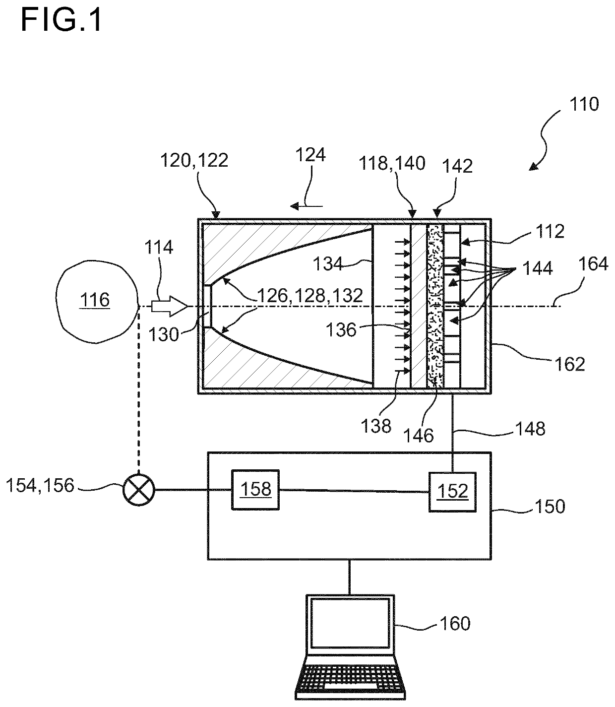
[0120]FIG. 1 illustrates, in a highly schematic fashion, an exemplary embodiment of a spectrometer system 110 which comprises a detector array 112 according to the present invention. As generally used, the spectrometer system 110 is designated for recording a signal intensity of incident light 114 with respect to a corresponding wavelength or a wavelength interval of the incident light 114 over a range of wavelengths which is denoted as a “spectrum” or as a partition thereof. According to the present invention, the spectrometer system 110 may, especially, be adapted for recording a spectrum in the infrared (IR) spectral region, preferably, in at least one of the near-infrared (NIR) and the mid-infrared (MidIR) spectral ranges, especially, wherein the incident light may have a wavelength of 1 μm to 5 μm, preferably of 1 μm to 3 μm, and can, thus, be applicable for investigation or monitoring purposes, in particular in the IR spectral region. Herein, the incident light 114 may be gene...


PUM


Abstract

Disclosed herein are a detector array, a spectrometer system including the detector array and a method of using of the spectrometer system. The detector array includes a substrate; and a plurality of detector pixels applied to a surface of the substrate, where each detector pixel has a sensor region which is designated for receiving a partition of incident light, where each detector pixel is designated for generating a sensor signal depending on an intensity of the partition of the incident light received by the sensor region of the detector pixel, where at least two adjacent detector pixels share a single connection to a common electric potential, and where the sensor regions of at least two of the detector pixels differ with respect to each other by an area of the corresponding sensor region.

Description

FIELD OF THE INVENTION[0001]The invention relates to a detector array and to a spectrometer system comprising the detector array, and to various uses of the spectrometer system. The spectrometer system can, generally, be employed for various investigation or monitoring purposes, in particular in the infrared (IR) spectral region, especially in at least one of the near-infrared (NIR) and the mid infrared (MidIR) spectral region. However, other kinds of applications are feasible.PRIOR ART[0002]Known spectrometer systems for the IR spectral region may, typically, be configured for transmission and / or reflection spectroscopy. For this purpose, the spectrometer device may comprise at least one wavelength selective element, such a linear variable filter element, a prism, a grating or the like, being configured for separating incident light into a spectrum of constituent wavelength signals. The respective intensities of those wavelength signals may be determined by employing at least one p...

Claims


Application Information

Patent Timeline
IPC IPC(8): G01J3/28G01J3/36
CPCG01J3/2803G01J3/2823G01J3/36G01J2003/2806G01J3/26G01J3/0227G01J3/0256G01J3/108
Inventor VALOUCH, SEBASTIANHERMES, WILFRIEDLUNGENSCHMIED, CHRISTOPHBRILL, JOCHENGUST, ROBERTSEND, ROBERTFEUERSTEIN, BERTRAMKLUEH, STEFAN
Owner TRINAMIX GMBH
Why Eureka
Try Eureka