
Dynamic adaptation of a dephasing gradient pair

a dephasing gradient and dynamic adaptation technology, applied in the field of dynamic adaptation of dephasing gradient pairs, can solve the problem of few raw data projections, and achieve the effect of accelerating the search for the correct bipolar dephasing gradient pair

Inactive Publication Date: 2015-03-10
SIEMENS HEALTHCARE GMBH
View PDF7 Cites 3 Cited by
  • Summary
  • Abstract
  • Description
  • Claims
  • Application Information

AI Technical Summary

Benefits of technology

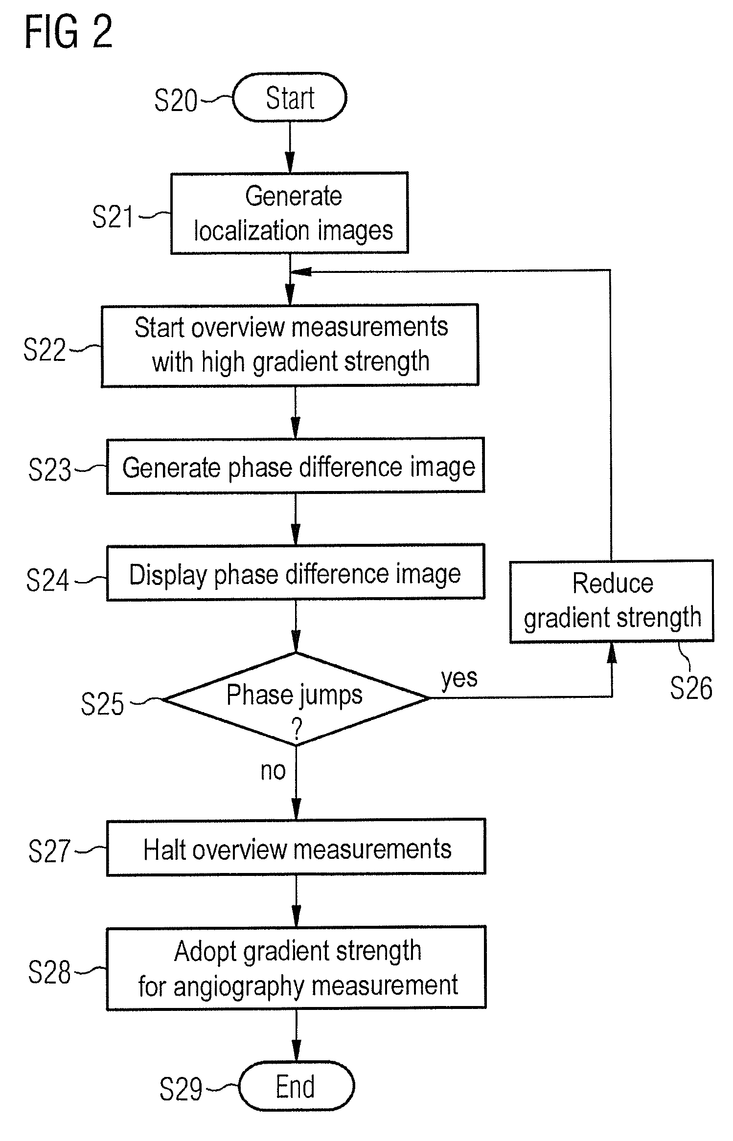
The present invention is about improving the search for the correct bipolar dephasing gradient pair in magnetic resonance phase contrast angiography. The invention provides a method optimization by switching a bipolar dephasing gradient pair based on the flow coding, which is used in the angiography. The strength of the flow coding is selected based on the flow velocity in the vessels to be depicted. Two partial measurements with different flow codings are implemented for each selected strength of the flow coding, and a phase difference image is automatically calculated and depicted in real time. The user can also interactively adjust various strengths of the flow coding for the next overview measurement, which accelerates the search for the ideal flow coding and results in better measurement results. The invention minimizes the number of projections required for the acquisition of the phase difference image by radial scanning of the raw MR data space. Overall, the invention improves the efficiency and accuracy of magnetic resonance phase contrast angiography.

Problems solved by technology

Radial scanning of raw data space results in only a very few projections of the raw data space having to be measured for the generation of the phase difference image with sufficient signal-to-noise ratio.

Method used


Image

  • Dynamic adaptation of a dephasing gradient pair
  • Dynamic adaptation of a dephasing gradient pair
  • Dynamic adaptation of a dephasing gradient pair

Examples


Embodiment Construction

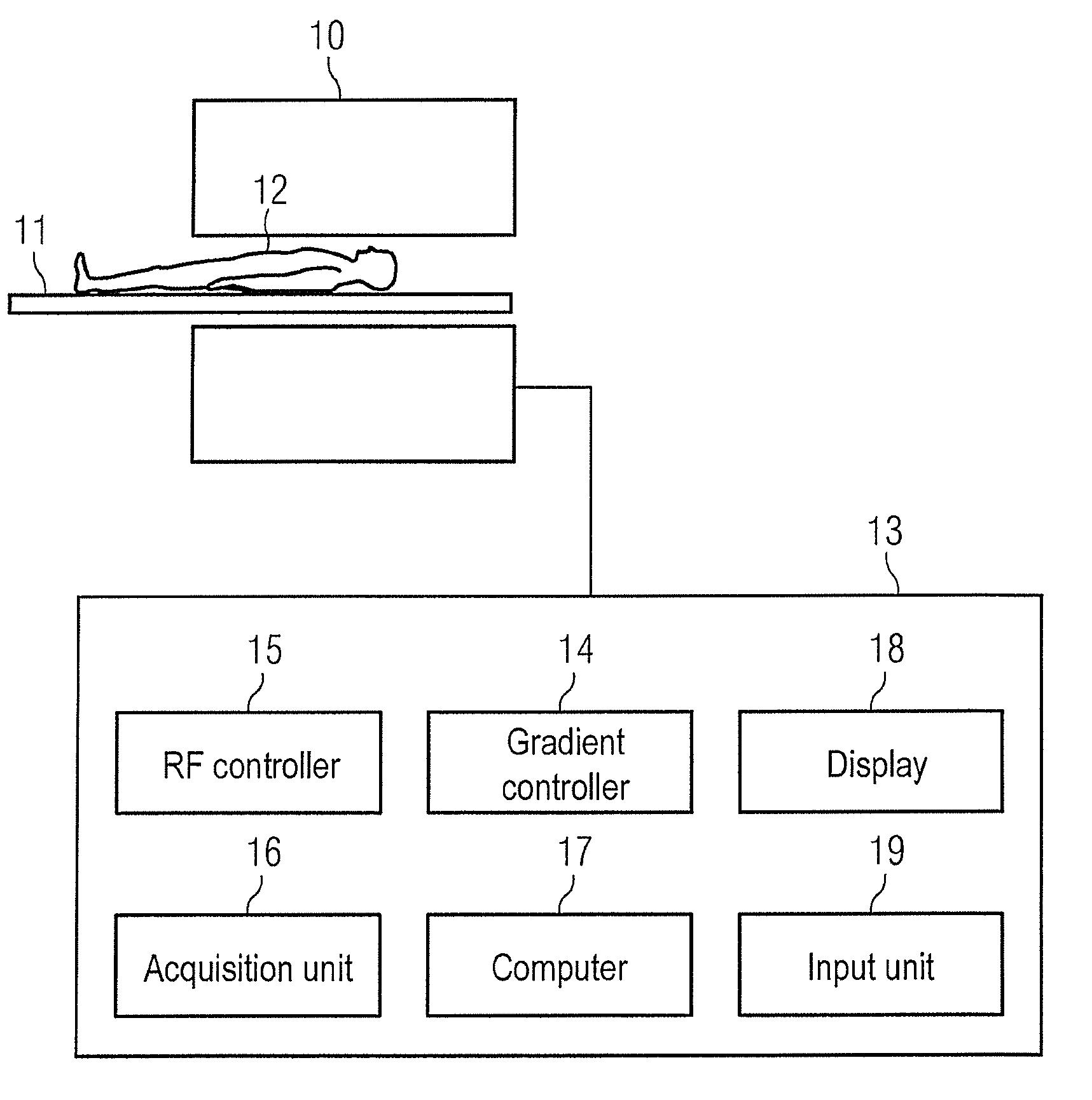
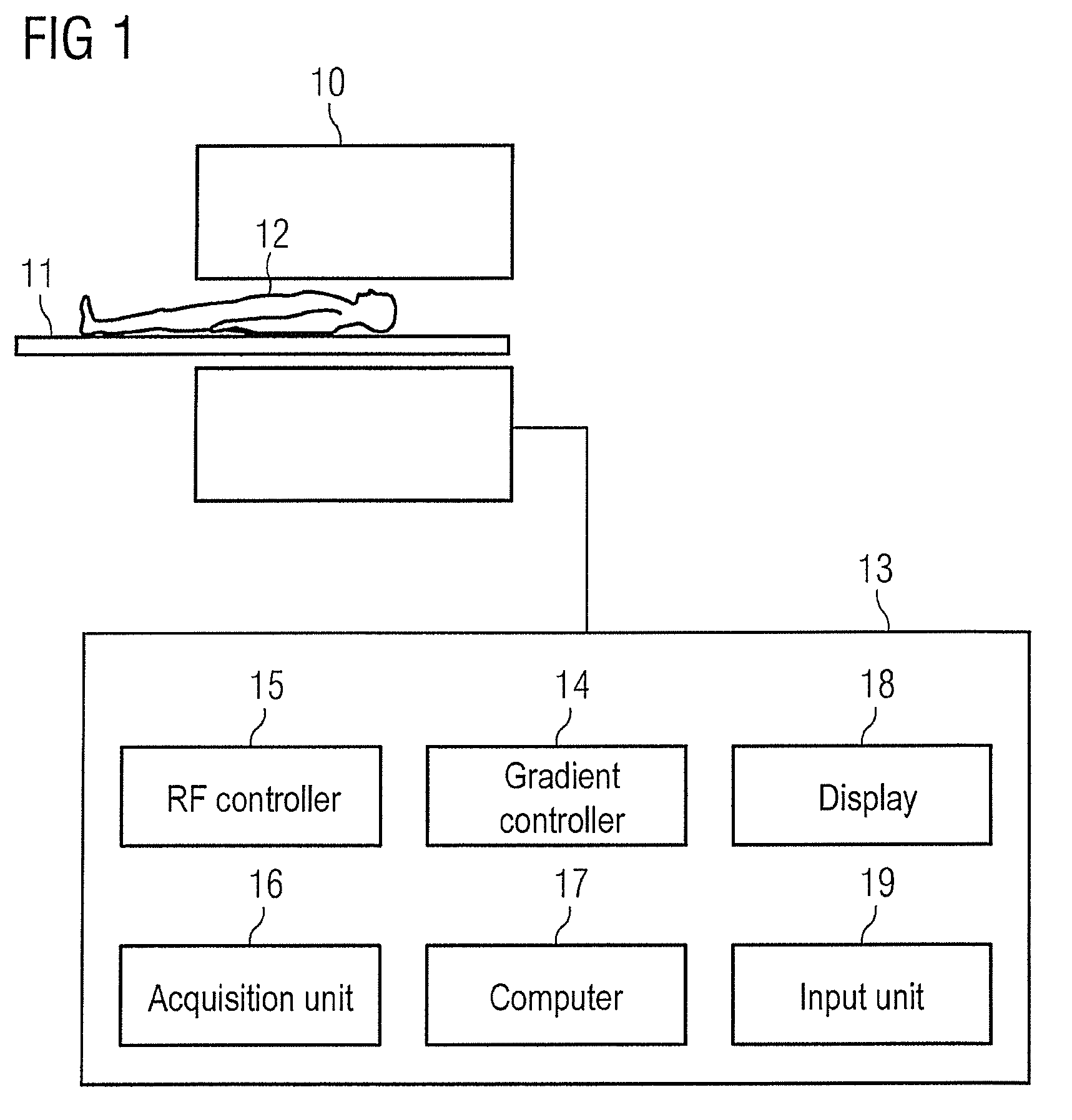
[0020]In FIG. 1, an MR system is shown with which a phase contrast angiography can be prepared effectively and quickly via determination of the correct bipolar dephasing gradient for coding the flow. The MR system has a magnet 10 to generate the polarization field B0. A person 12 to be examined, arranged on a bed 11, is driven into the magnet, and the voltages generated after radiation of RF pulses in connection with switched gradients are detected by a reception coil (not shown) and transferred to a central control unit 13. The central control unit 13 has a gradient controller 14 with which the magnetic field gradients that are necessary for spatial coding of the signals are controlled. An RF controller 15 controls the radiations of the RF fields to generate the MR signals by flipping the magnetization out of the steady state. An acquisition unit 16 controls the workflow of the gradient fields and the radiated RF pulses depending on the selected imaging sequence and thus controls t...


PUM


Abstract

In a method for optimization of a flow coding with switching of an additional bipolar dephasing gradient pair, used in a magnetic resonance (MR) phase contrast angiography, the strength of the flow coding is selected depending on the flow velocity in the vessels that should be depicted. MR signals of an examination region are acquired with continuously running overview measurements, with an operator-selected flow coding strength. After the selected flow coding strength is adopted automatically for the next measurement of the continuously running overview measurements, and two partial measurements with different flow codings are implemented for each selected strength and a phase difference image from the two partial measurements is calculated and depicted in real time, and the selected flow coding strength is automatically adopted for the MR phase contrast angiography.

Description

BACKGROUND OF THE INVENTION[0001]1. Field of the Invention[0002]The present invention concerns a method to optimize a flow coding that is achieved by switching of an additional bipolar dephasing gradient pair that is used in a magnetic resonance phase contrast angiography measurement (data acquisition), wherein the strength of the flow coding is selected depending on the flow rate in the vessels with which the magnetic resonance phase contrast angiography measurement should be depicted. The invention furthermore concerns a MR system to implement the method.[0003]2. Description of the Prior Art[0004]In phase contrast angiography by means of nuclear magnetic resonance, the phase effects of flowing spins are used in order to depict them. These phase effects are based on the fact that, given a bipolar gradient pulse, excited spins that move along a magnetic field gradient have a different phase curve than resting spins. With resting spins, given switching of a bipolar gradient moment th...

Claims


Application Information

Patent Timeline
Patent Type & Authority Patents(United States)
IPC IPC(8): G01R33/44G01R33/54G01R33/563
CPCG01R33/56316G01R33/543G01R33/5635
Inventor GREISER, ANDREASSPEIER, PETER
Owner SIEMENS HEALTHCARE GMBH
Learn More