Dual-brering reel

a reel and reel body technology, applied in the field of dual-breathing reels, can solve the problems of spool shaft and pinion gear colliding, affecting the operation of the reel, and causing the generation of abnormal nois

Active Publication Date: 2019-06-27
SHIMANO INC
View PDF7 Cites 6 Cited by
  • Summary
  • Abstract
  • Description
  • Claims
  • Application Information

AI Technical Summary

Benefits of technology

[0015]According to the present invention, the generation of abnormal noise caused by the collision between the spool shaft and the pinion gear can be prevented, movemen...

Problems solved by technology

In a state in which a large load is applied to the pinion gear, if the elastic member contracts and the pinion gear moves in the axial direction, the meshing between the pinion gear and the drive gear becomes unstable, and the meshing between the pinion gear and the drive gear can be subject to int...

Method used


Image

  • Dual-brering reel
  • Dual-brering reel
  • Dual-brering reel

Examples


Embodiment Construction

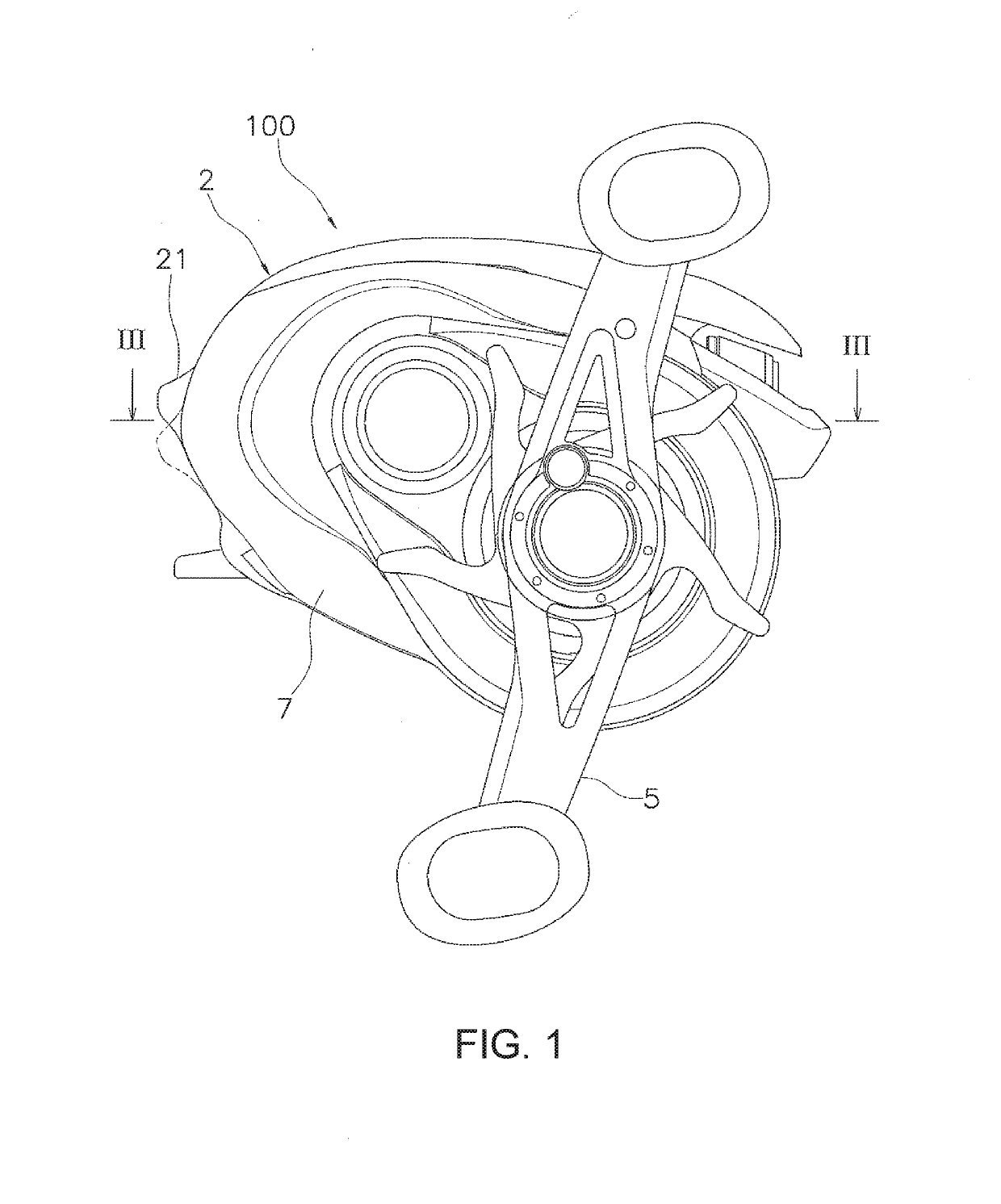
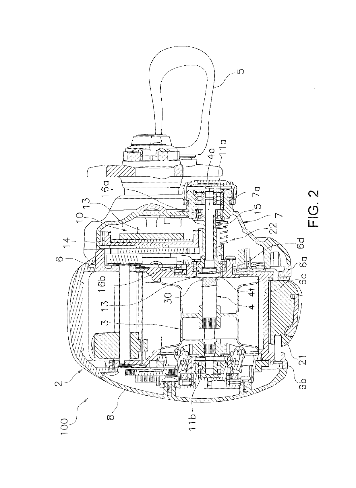
[0022]As shown in FIGS. 1 and 2, a dual-bearing reel 100 in which one embodiment of the present invention is employed comprises a reel body 2, a spool 3, a spool shaft 4, a handle 5, a rotation transmission mechanism 10, a clutch mechanism 20, and an elastic member 30. FIG. 1 is a side view of the reel body 2 as seen from the handle 5 side.

[0023]In the following description, the direction in which a fishing line is cast (unreeled) during fishing is referred to as the front, and the opposite direction is referred to as the rear. Additionally, left and right refer to left and right when the dual-bearing reel 100 is seen from the rear. In addition, the direction in which the spool shaft 4 extends is referred to as the axial direction. Additionally, the direction that is orthogonal to the direction in which the spool shaft 4 extends is referred to as the radial direction.

[0024]As shown in FIG. 2, the reel body 2 comprises a frame 6, a first side cover 7, and a second side cover 8. The f...


PUM


Abstract

A dual-bearing reel includes a handle, a spool, a spool shaft, a clutch mechanism, a pinion gear, and an elastic member. The spool shaft is connected to the spool to be integrally rotatable and has a first abutting portion. The pinion gear has a second abutting portion to abut the first abutting portion in the axial direction in the inner circumferential portion thereof, and can move in the axial direction between a coupled position, in which the pinion gear is connected to the spool shaft so as to be integrally rotatable, and a decoupled position, in which the connection is disconnected. When the pinion gear is in the coupled position, the elastic member contacts the distal end of the pinion gear and biases the first abutting portion and the second abutting portion in directions away from each other.

Description

CROSS-REFERENCE TO RELATED APPLICATIONS[0001]This application claims priority to Japanese Patent Application No. 2017-250835, filed on Dec. 27, 2017. The entire disclosure of Japanese Patent Application No. 2017-250835 is hereby incorporated herein by reference.BACKGROUNDField of the Invention[0002]The present invention relates to a dual-bearing fishing reel.Background Art[0003]Dual-bearing reels include a clutch mechanism for transmitting and preventing the rotational force of a handle. The clutch mechanism is generally disposed between the spool shaft and a pinion gear. The pinion gear can move in the axial direction between a coupled position, in which the pinion gear is connected to the spool shaft so as to be integrally rotatable, and a decoupled position, in which the connection with the spool shaft is released. The pinion gear meshes with a drive gear, to which the rotational force of the handle is transmitted (refer to Japanese Utility Model Registration No. 2575471).[0004]I...

Claims


Application Information

Patent Timeline
IPC IPC(8): A01K89/015
CPCA01K89/0189A01K89/0193A01K89/015A01K89/01931A01K89/0186
Inventor OOGOSE, HIROKIMARUOKA, TAKANORITAKECHI, KUNIO
Owner SHIMANO INC
Why Eureka
Try Eureka