Recording device and control method for recording device

Active Publication Date: 2019-06-27
SEIKO EPSON CORP
View PDF0 Cites 8 Cited by
  • Summary
  • Abstract
  • Description
  • Claims
  • Application Information

AI Technical Summary

Benefits of technology

[0017]When the time for acquiring the second current profile is shortened, waiting time (downtime) of

Problems solved by technology

Therefore, each time the transport speed mode is changed, the reference current measurement operation becomes nec

Method used


Image

  • Recording device and control method for recording device
  • Recording device and control method for recording device
  • Recording device and control method for recording device

Examples


Example

[0031]An exemplary embodiment of the invention is described below with reference to the accompanying drawings. The exemplary embodiment is merely illustrative, and the invention is not limited to the exemplary embodiment. The exemplary embodiment can be modified as desired without departing from the scope of the technical concept of the invention. Additionally, in each of the following drawings, to make each layer, each member, and the like recognizable in terms of size, each of the layers, members, and the like is illustrated in a scale different from an actual scale.

Exemplary Embodiment

[0032]Overview of Recording Device

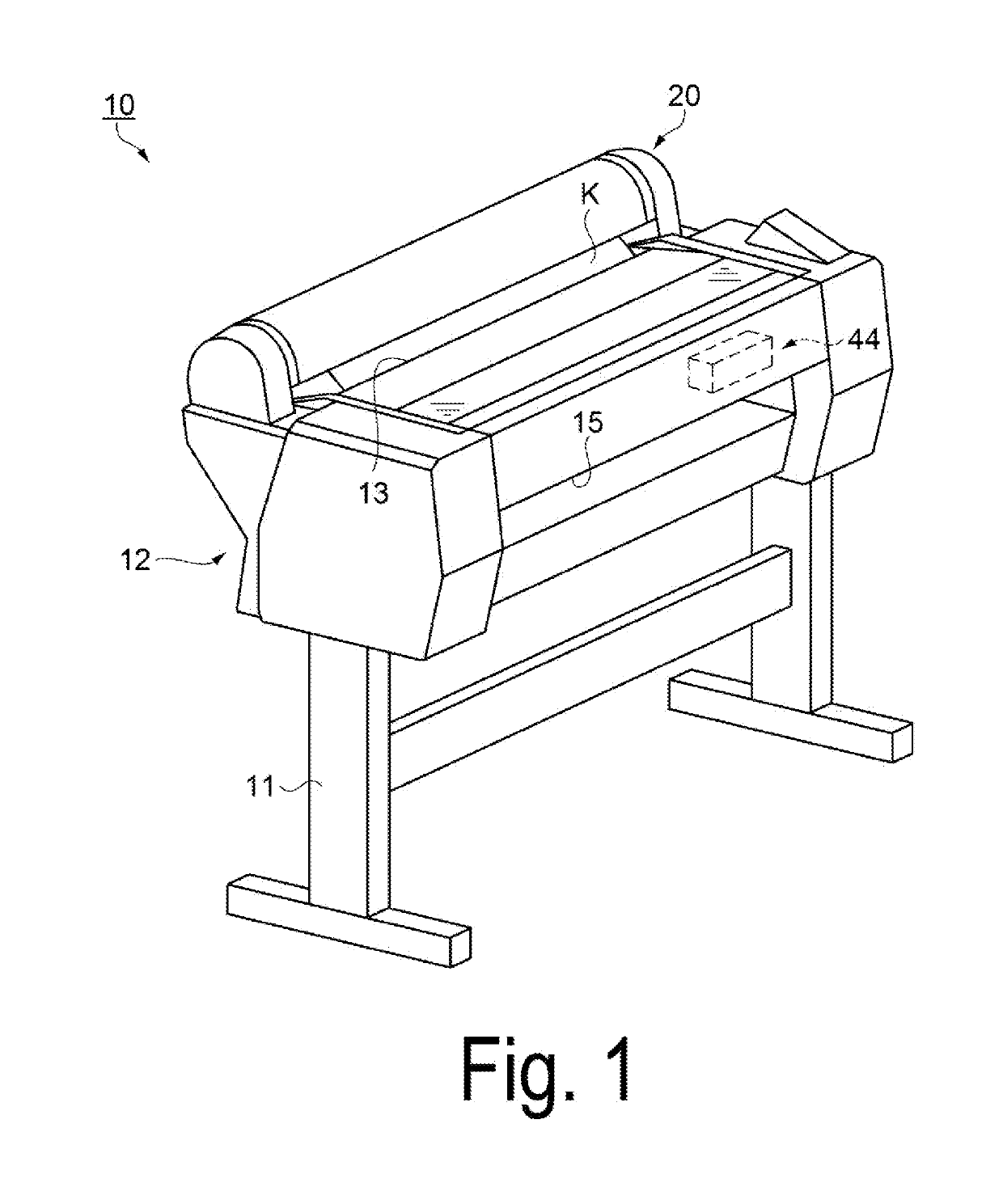
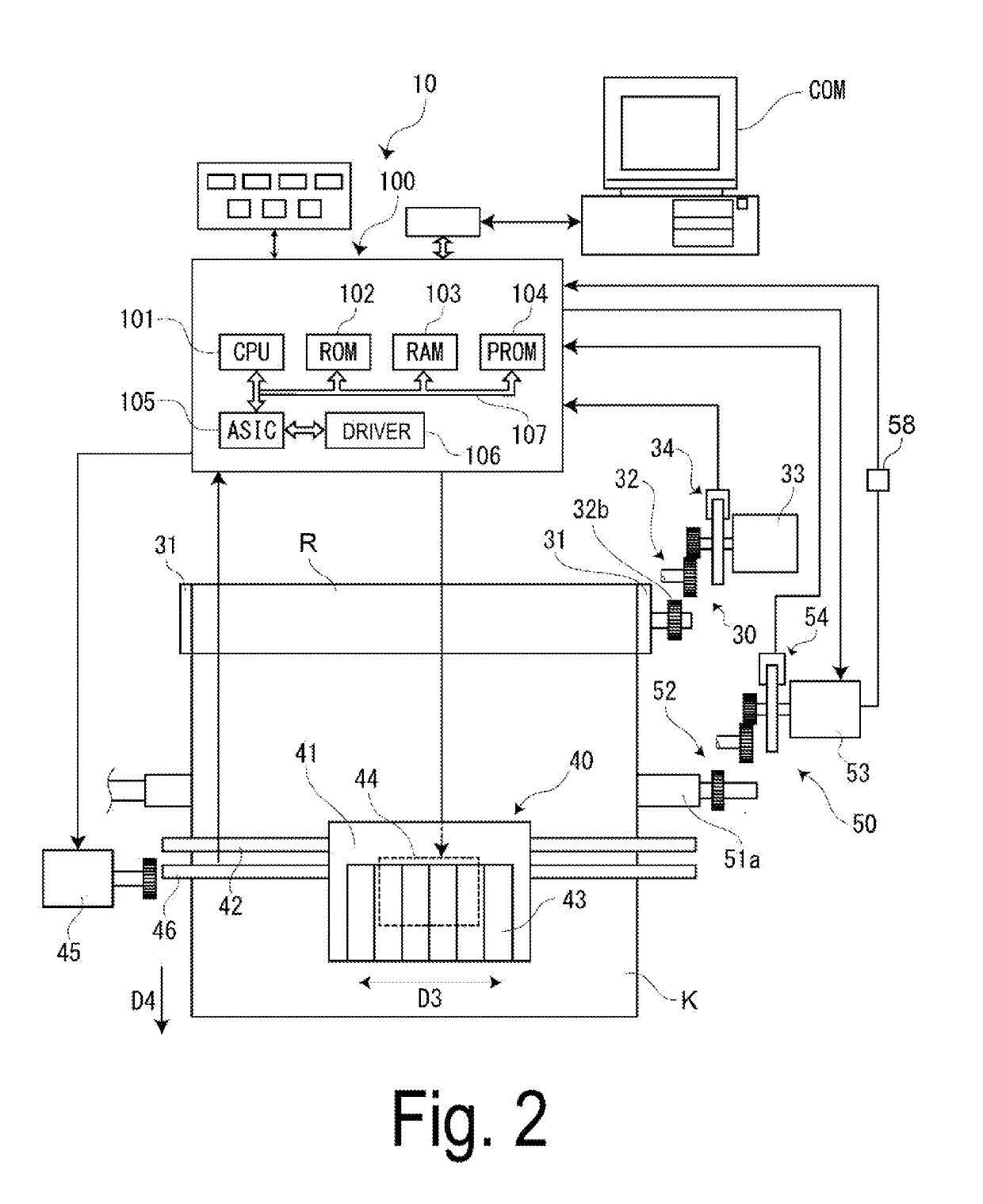
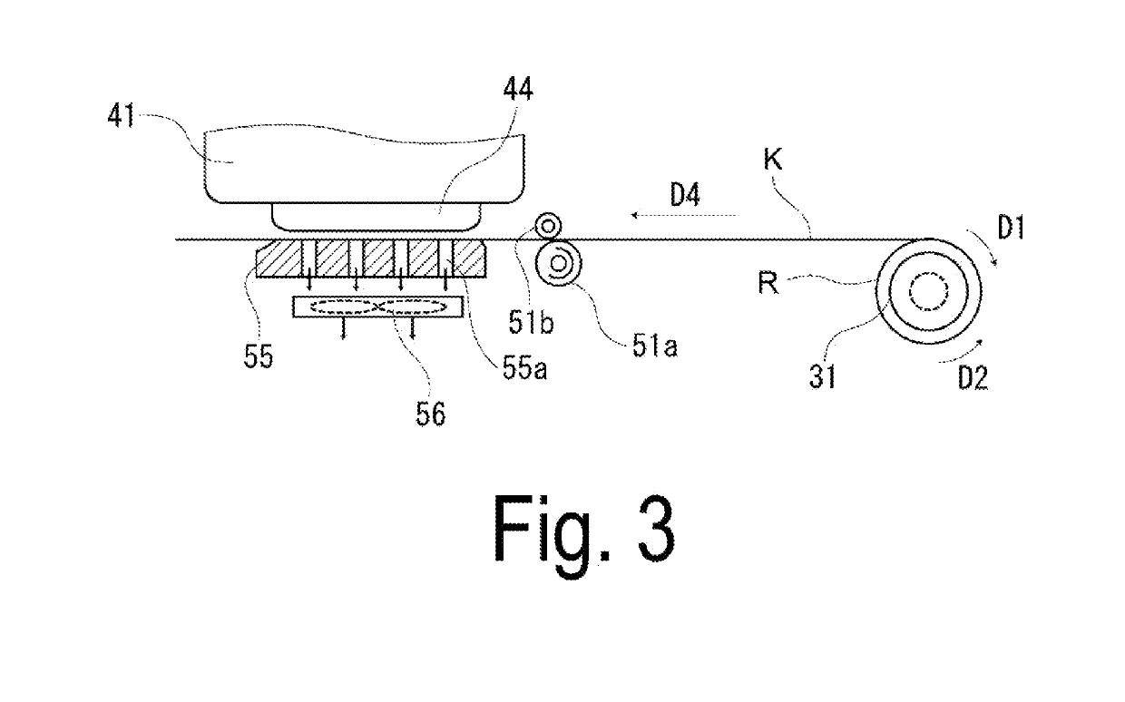
[0033]FIG. 1 is a perspective view of a recording device according to an exemplary embodiment. FIG. 2 is a schematic view illustrating a schematic configuration of the recording device according to the exemplary embodiment. FIG. 3 is a schematic view illustrating a state of a case where an image is recorded on a medium. FIG. 4 is a block diagram illustrating a funct...


PUM


Abstract

A recording device includes: a transport unit configured to transport a medium in a plurality of transport speed modes; a driving unit configured to drive the transport unit with a plurality of speed profiles, each corresponding to one of the plurality of transport speed modes; a current sensor configured to measure a reference current the driving unit, the reference current being a current flowing in the driving unit when the medium is transported in a loosened state; and a control configured to acquire a plurality of current profiles, each corresponding to one of the speed profiles, based on the reference current. The control unit is configured to acquire a first current profile based on the reference current when the medium is transported in a first transport speed mode, and to generate a second current profile based on the first current profile.

Description

CROSS-REFERENCE TO RELATED APPLICATION[0001]This application claims priority under 35 U.S.C. § 119 to Japanese Patent Application No. 2017-245962, filed Dec. 22, 2017, the disclosure of which is hereby incorporated by reference in its entirety.BACKGROUND1. Technical Field[0002]The invention relates to a recording device and a control method for a recording device.2. Related Art[0003]For example, a medium transport device (recording device) configured to repeat an operation of discharging ink from a recording head to form a dot, and an operation of transporting a medium (transport operation), and configured to record an image on the medium pulled out of a roll paper (roll body) has been proposed (e.g., JP-A-2015-231910). The recording device described in JP-A-2015-231910 includes a retention unit configured to retain a roll body formed with a medium wound, a transport unit configured to pull the medium out of the roll body and transport the medium, a roll motor configured to rotate t...

Claims


Application Information

Patent Timeline
IPC IPC(8): B65H20/02B41J13/00G01R19/00
CPCB65H20/02B41J13/0009G01R19/0092B65H2403/92B41J11/425B65H23/1825B65H23/185B65H23/1888B65H23/192B65H2553/51B65H2513/11B65H2515/32B65H2801/36B65H2220/01B65H2220/02B65H2220/03B65H20/005B65H23/18B65H23/182B65H2557/20
Inventor HAMANO, RYO
Owner SEIKO EPSON CORP
Why Eureka
Try Eureka