Automated measurements on drill cuttings while drilling

a drilling cutting and drilling technology, applied in the direction of instruments, measurement using nmr, borehole/well accessories, etc., can solve the problems of high cost and functional limitations of measurement types, insufficient throughput and functionality to support drilling process, and inability to address earth formation evaluation techniques

Inactive Publication Date: 2019-07-11
REIDERMAN ARCADY
View PDF0 Cites 3 Cited by
  • Summary
  • Abstract
  • Description
  • Claims
  • Application Information

AI Technical Summary

Benefits of technology

[0007]One aspect of the present disclosure is an apparatus for automated measurements on drill cuttings comprising a catcher to collect a portion of the drill cuttings directly from a shaker, an at least one pneumatic actuator to move the collected portion of the drill cuttings from the catcher into a measurement sensitivity area created by a measurement module, the measurement module having a hermetically sealed enclosure. The sensitivity area is formed outside the enclosure and surrounded by the measurement module. The measurement module and the pneumatic actuator are controlled by an external control and data processing unit placed away from the oil well. The apparatus may also comprise a guide to define a rate of the cuttings collecting in the catcher. The measurement module can be a nuclear magnetic resonance (NMR) measurement module or other measurement modules that perform bulk sensitive measurements.

Problems solved by technology

This type of measurements is typically high cost and functionally limited.
These measurements are typically done in laboratory, their throughput and functionality are not adequate to support the drilling process.
The technique does not address the earth formations evaluation.
The teaching does not address the earth formations characterization while drilling.

Method used


Image

  • Automated measurements on drill cuttings while drilling
  • Automated measurements on drill cuttings while drilling
  • Automated measurements on drill cuttings while drilling

Examples


Embodiment Construction

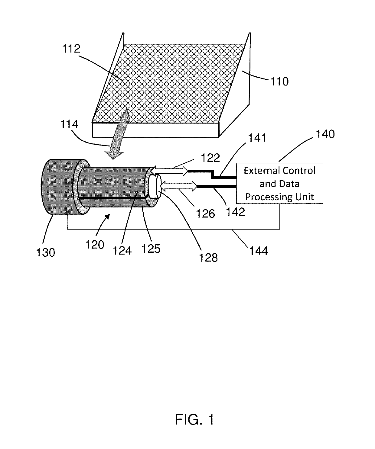
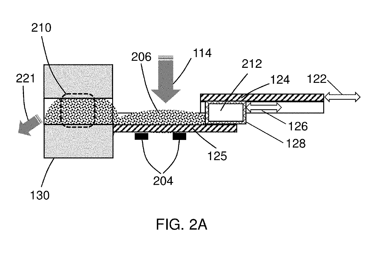
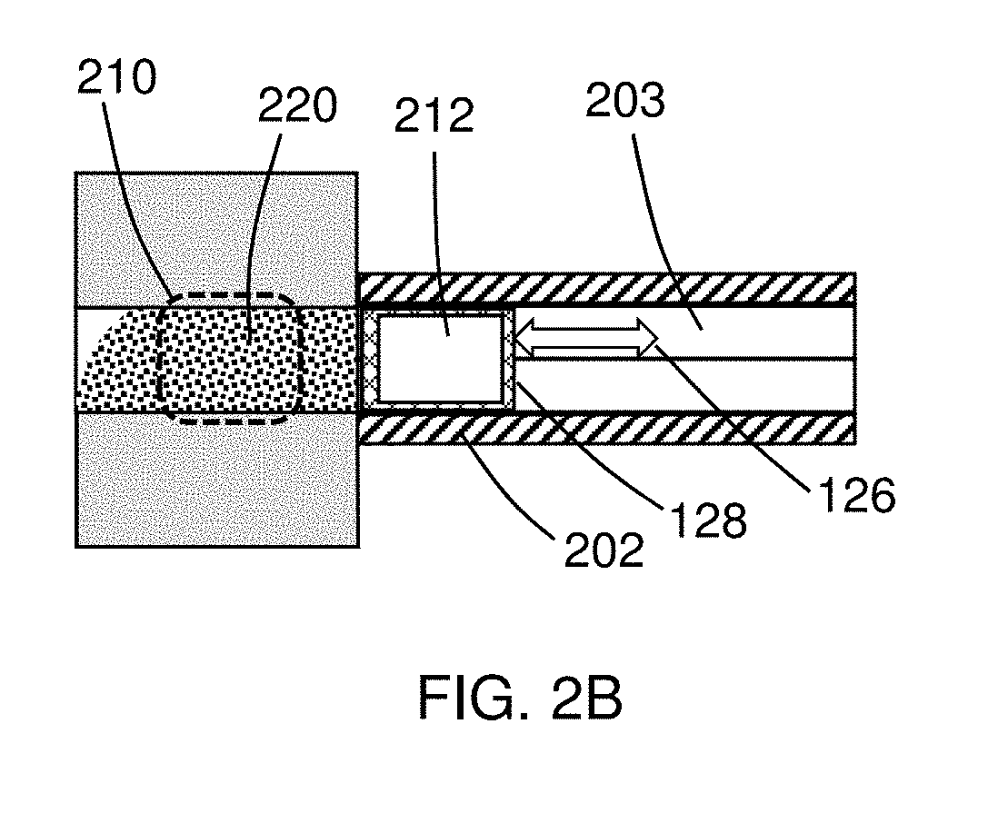
[0015]FIG. 1 illustrates an isometric view of a portion of the apparatus according to an embodiment disclosed. The drilling mud is passed through vibrating sieves 112 mounted on a shaker 110 where the rock cuttings (also called drill cuttings) are separated from the drilling mud (using the vibrating sieves). The separated cuttings fall over the edge of the sieves (the drill cuttings path is shown at 114) into is a sample catcher module 120 collecting the drill cuttings. The apparatus includes a measurement module 130 that forms a measurement sensitivity area (not shown in FIG. 1) to performs a bulk sensitive measurement (e.g. an NMR relaxation measurement) on the collected portion of the drill cuttings. The sample catcher module has a first pneumatic actuator 122 to control a cover 124 and a second pneumatic actuator 126 to move the cuttings collected in a catcher 125 (shown in FIG. 1 as a lower half pipe) into a measurement sensitivity area (not shown in FIG. 1). A sample piston 12...


PUM

PropertyMeasurementUnit
nuclear magnetic resonance measurementsaaaaaaaaaa
natural gamma spectroscopyaaaaaaaaaa
weightaaaaaaaaaa

Abstract

An apparatus (and method) for automated measurements on drill cuttings comprising a sample catcher to collect a portion of the drill cuttings directly from a shaker, an at least one pneumatic actuator to move the collected portion from the sample catcher into a measurement sensitivity area created by a measurement module. The measurement module has a hermetically sealed enclosure and placed near the sample catcher. The sensitivity area is formed outside the enclosure and surrounded by the measurement module. The measurement module and the pneumatic actuator are controlled by an external unit placed away from the shaker. The measurement module can be a nuclear magnetic resonance (NMR) measurement module or other measurement module that performs high-throughput bulk sensitive measurements.

Description

BACKGROUND OF THE INVENTIONField of the Invention[0001]This invention is related to evaluation of petrophysical properties of the earth formations while drilling an oil well. More specifically, the invention teaches methods and apparatus for evaluating petrophysical properties of the earth formations using measurements on drill cuttings. The measurements may include nuclear magnetic resonance (NMR) relaxometry.Background Art[0002]Formations evaluation including NMR measurements can be done while drilling using well logging instruments placed on a drill collar. This type of measurements is typically high cost and functionally limited.[0003]Advanced mud logging including measurements on drill cuttings is another known approach to formations evaluation while drilling (US20060272812). These measurements are typically done in laboratory, their throughput and functionality are not adequate to support the drilling process.[0004]US20170161885 teaches measurements on drill cuttings while the...

Claims


Application Information

Patent Timeline
Patent Type & Authority Applications(United States)
IPC IPC(8): G01N24/08E21B21/01E21B49/00E21B49/08G01R33/44G01V3/32G01V3/38G01V5/12G06K9/62G05B13/04
CPCG01N24/081E21B21/01E21B49/003E21B49/08G01R33/448G01V3/32G01V3/38G01V5/12G06K9/6201G05B13/042E21B7/00E21B2049/085G01V5/045E21B49/005E21B49/0875G06F18/22
Inventor REIDERMAN, ARCADY
Owner REIDERMAN ARCADY
Why Eureka
Try Eureka