Engine autostop control

a technology of engine and control panel, applied in electric vehicle charging technology, transportation and packaging, propulsion parts, etc., can solve problems such as friction that generates negative engine torqu

Active Publication Date: 2019-07-18
TOYOTA JIDOSHA KK
View PDF4 Cites 7 Cited by
  • Summary
  • Abstract
  • Description
  • Claims
  • Application Information

AI Technical Summary

Benefits of technology

[0010]In accordance with another embodiment, a hybrid electric vehicle towing a trailer may comprise an internal combustion engine; an electric motor operatively connected in parallel to the internal combustion engine; and an electronic control unit. The electronic control unit may be adapted to control operation of the internal combustion engine in accordance with one or more control signals from an engine autostop control circuit. Thus, the electronic control unit can be instructed to turn the internal combustion engine off upon the hybrid electric vehicle reaching a threshold vehicle speed at which the electric motor can recoup all available energy through regenerative braking and the hybrid electric vehicle is decelerating.
[0011]In some embodiments, the electronic control unit is adapted to further control operation of the internal combustion engine in accordance with additional one or more control signals from the engine autostop control circuit. These signals can instruct the electronic control unit to keep the internal combustion engine on when the hybrid electric vehicle is traveling at a speed that surpasses the threshold vehicle speed.
[0012]In some embodiments, the engine autostop control circuit calculates potential available energy that can be recouped through regenerative braking. In some embodiments, the engine autostop control circuit calculates the potential available energy that can be recouped based on force absorbed by brakes of the trailer during deceleration of the hybrid electric vehicle.
[0013]In some embodiments, the engine autostop control circuit calculates the potential available energy that can be recouped based additionally on mass and road load of the hybrid electric vehicle and the trailer. In some embodiments, the engine autostop control circuit calculates the potential available energy that can be recouped based additionally on an anticipated deceleration due to braking by a driver of the hybrid electric vehicle.

Problems solved by technology

This results in friction that generates negative engine torque.

Method used


Image

  • Engine autostop control
  • Engine autostop control
  • Engine autostop control

Examples


Embodiment Construction

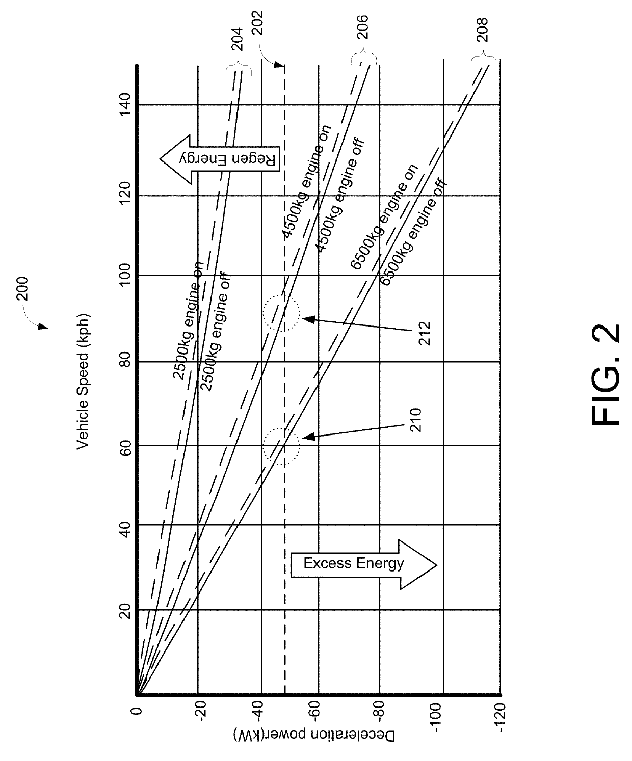
[0030]Depending on certain factors, energy that can be recaptured by an HEV (while towing a load, such as a trailer) through regenerative braking varies. Those factors may include vehicle speed, mass and road load of a vehicle towing the trailer, battery state of charge (SOC), vehicle and trailer brake characteristics, and driving characteristics of a driver. For example, under certain conditions, e.g., when a vehicle is traveling at higher speeds and its mass along with that of a trailer is high, energy loss due the engine being in fuel cut mode cannot be recaptured. Additionally, the benefits of recapturing energy can be outweighed by the startup energy required to reach the necessary drive force to propel the vehicle and its trailer depending on the above factors. Further still, the point at which all the available energy can begin to be recaptured may depend on how aggressively the driver brakes in order to decelerate the HEV.

[0031]In those cases when it would not be beneficial ...


PUM


Abstract

Systems and methods are provided for determining an optimal point during operation of a hybrid electric vehicle towing a trailer at which the energy that can be recouped through regenerative braking is maximized. Operating conditions or characteristics of the hybrid electric vehicle and the brake characteristics of the trailer are considered in determining the optimal point at which the energy that can be recouped is maximized. At the optimal point at which the energy that can be recouped is maximized, the engine of the hybrid electric vehicle is turned off. Otherwise, the engine of the hybrid electric vehicle is left on.

Description

TECHNICAL FIELD[0001]The present disclosure relates generally to controlling engine operation in a hybrid electric vehicle (HEV). In some embodiments, enablement of the autostop feature in an HEV is inhibited based on a surplus of regenerative braking potential energy and lack of fuel economy benefits during a tow condition.DESCRIPTION OF RELATED ART[0002]Hybrid electric vehicles (HEVs) have become increasingly popular among drivers concerned with their environmental impact and with increasing fuel economy. HEVs generally utilize an internal combustion engine (ICE) in conjunction with an electric motor, also referred to as a motor generator (MG). HEVs can achieve better fuel economy over a conventional (ICE-only) vehicle because the need for fossil fuel, e.g., gasoline, is reduced. HEVs also help reduce the carbon footprint of an individual by lessening the creation of toxic byproducts normally generated when operating a conventional fossil-fuel-powered vehicle. An HEV's electric mo...

Claims


Application Information

Patent Timeline
Patent Type & Authority Applications(United States)
IPC IPC(8): B60W20/10B60W30/18B60W40/13B60W40/10B60L7/18B60L15/20
CPCB60W20/10B60W30/18109B60W40/13B60W40/10B60L7/18B60L15/2009B60W2530/10B60W2540/12B60W2520/105B60W2510/182B60W2710/06B60W2710/18B60K6/48B60K2006/4825B60L7/26B60L2200/28B60L2240/12B60L2240/642B60L2250/18B60L2260/50B60W30/18127B60W50/0098B60W2050/0075B60W2520/10B60W2540/30B60W2530/203B60W2556/10Y02T10/62Y02T10/64Y02T10/72Y02T90/16
Inventor HAWLEY, THOMAS S.
Owner TOYOTA JIDOSHA KK
Why Eureka
Try Eureka