Rotary connector and fixing structure of rotary connector

a technology of fixing structure and rotary connector, which is applied in the direction of flexible/turnable line connectors, coupling device connections, transportation and packaging, etc., can solve the problems of affecting the service life and requiring space between the rotary connector. to prevent looseness and unexpected lifting of the rotary connector

Active Publication Date: 2019-07-18
FURUKAWA ELECTRIC CO LTD +3
View PDF3 Cites 3 Cited by
  • Summary
  • Abstract
  • Description
  • Claims
  • Application Information

AI Technical Summary

Benefits of technology

The invention can stop the rotary connector from getting loose or lifting unexpectedly.

Problems solved by technology

Hence there is a drawback that looseness occurs in a direction in which the projecting piece 103 is inserted.
When such looseness occurs, an abnormal sound tends to occur.
However, a space is required between the rotary connector and the combination switch, and furthermore, extra materials and members are required.
This makes it impossible to reduce the size and cost.
Especially, when the cushioning material is provided, deterioration in the material and dropout of the cushioning material are considered, and it is difficult to maintain the effect.

Method used


Image

  • Rotary connector and fixing structure of rotary connector
  • Rotary connector and fixing structure of rotary connector
  • Rotary connector and fixing structure of rotary connector

Examples


Embodiment Construction

[0047]An embodiment for carrying out the present invention will be described below with reference to the drawings.

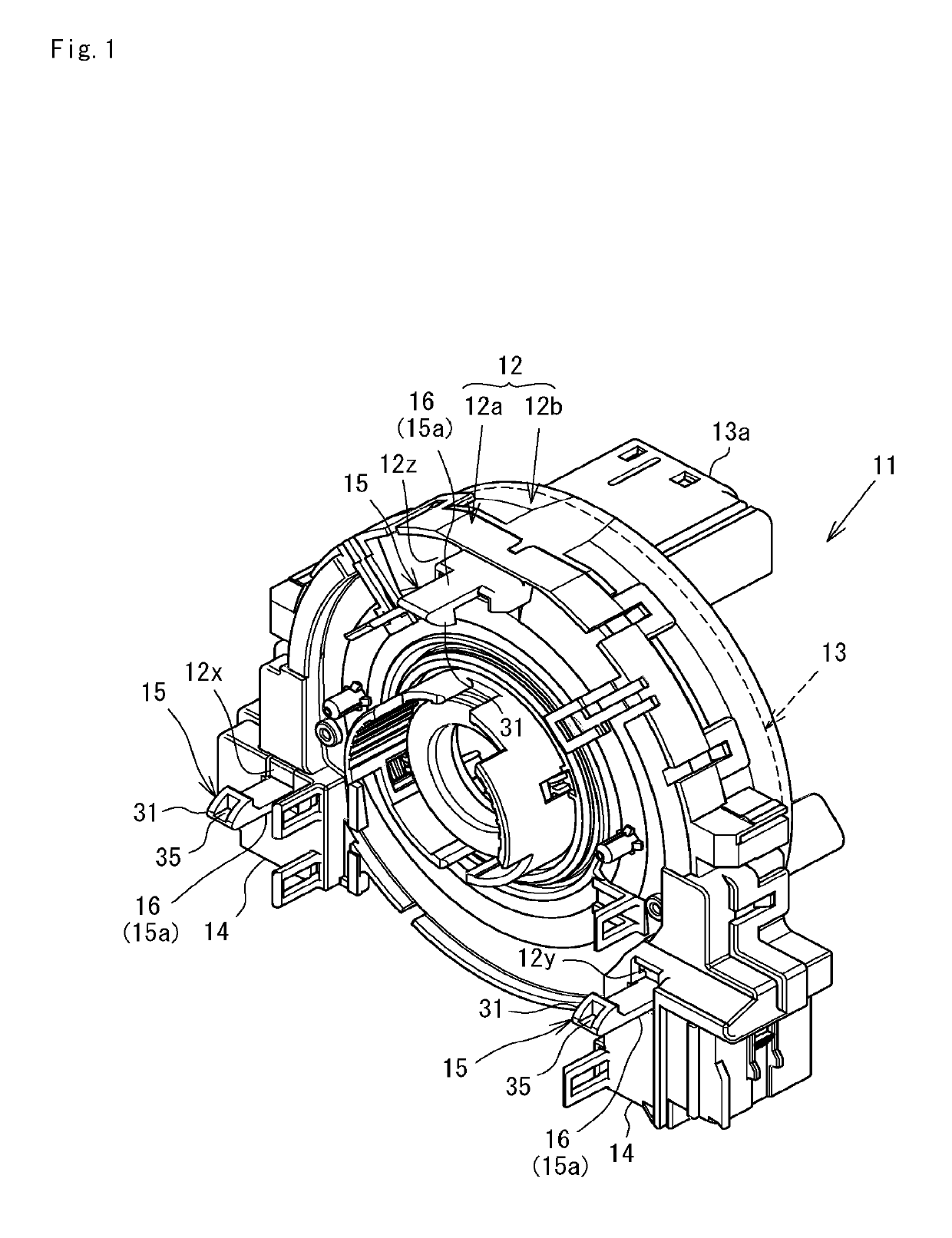
[0048]First, a schematic structure of a rotary connector 11 shown in FIG. 1 will be described.

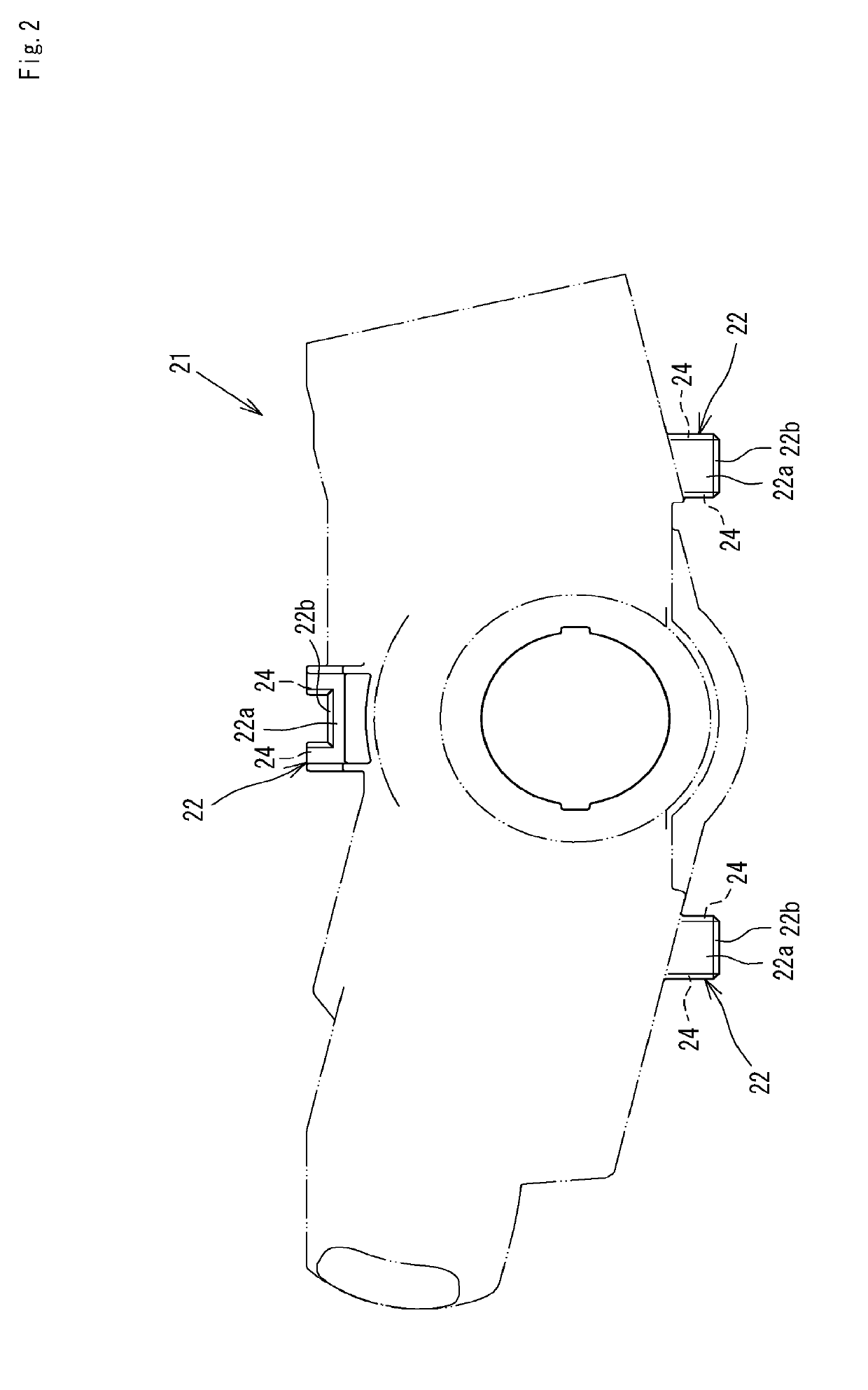
[0049]This rotary connector 11 electrically connects a steering wheel and a combination switch in a car. FIG. 1 shows the lower surface of the rotary connector 11, namely, the surface on the side which is fixed to the combination switch 21 shown in FIG. 2. A plurality of receiving portions 22 are formed in the combination switch 21 for the fixing.

[0050]The rotary connector 11 has a substantially annular shape with a circular hole at the center, and is provided with a stator 12 as a fixed side member located on the lower surface side, and a rotator 13 as a rotary side member located on the upper surface side. The stator 12 and the rotator 13 are made of synthetic resin.

[0051]The stator 12 is made up of a fixed side ring plate member 12a having a substantially annular shape, and a...


PUM


Abstract

Looseness of a rotary connector and lifting of the rotary connector which occurs depending on a harness wiring state are prevented, to reduce inconvenience such as generation of an abnormal sound due to the rotary connector contacting a steering wheel.In a fixing structure of a rotary connector, which includes a projecting piece 15 to fix the rotary connector to a combination switch and a locked portion 22a to be locked by the projecting piece 15 and in which a laterally protruding locking claw 31 is formed in a tip portion of the projecting piece 15, the locking claw 31 of the projecting piece 15 is integrally provided with a flexible urging portion 15a that displaces and urges the locking claw 31 in a locking direction. A contact surface 32 is formed on the locking claw 31, the contact surface 32 obliquely coming into contact with a locking side corner 23 of the locked portion 22a from the opposing side

Description

TECHNICAL FIELD[0001]The present invention relates to a rotary connector for fixing a rotary connector provided below a steering wheel of a vehicle to a combination switch, and more particularly to a rotary connector capable of preventing generation of an abnormal sound in a fixed state.BACKGROUND ART[0002]The rotary connector is used as electrical connection means of, for example, an air bag system. The rotary connector includes a rotator fixed to a steering wheel mounted with an air bag, and a stator rotatably supporting the rotator, and accommodates a flexible flat cable in a wound state in an internal space formed by the rotator and the stator. With this configuration, even when the rotator rotates with the rotation of the steering wheel, the electrical connection state can be maintained.[0003]In a fixing structure for fixing the rotary connector to the combination switch, locking is used so that fixing work can be performed more easily as compared to the case of using a screw. ...

Claims


Application Information

Patent Timeline
Patent Type & Authority Applications(United States)
IPC IPC(8): H01R35/04B60R16/027B62D1/10H01R35/02H01R39/02H01R12/70
CPCH01R35/04B60R16/027B62D1/10H01R35/025H01R39/02H01R12/7011H01R2201/26
Inventor HIRAI, SHUJIKAMIYA, KAZUTAKAKOSUGI, TOSHIHIKOSHIGEYAMA, SHIGEOISHIGURE, NOBUYUKICHIBA, YOSHIOIKEGAME, KUNIHIKOMATSUMURA, HIDEKIUSUYA, TADASHI
Owner FURUKAWA ELECTRIC CO LTD
Why Eureka
Try Eureka