Endoscope system and method of operating same

a technology of endoscope and endoscope, which is applied in the field of endoscope system, can solve the problems of user burden and user experience visual discomfort, and achieve the effect of reducing visual discomfor

Inactive Publication Date: 2019-07-18
FUJIFILM CORP
View PDF1 Cites 4 Cited by
  • Summary
  • Abstract
  • Description
  • Claims
  • Application Information

AI Technical Summary

Benefits of technology

[0017]According to the invention, even in a case where the normal image and the special image are alternately displayed, it is possible to reduce visual discomfort such as eye flickering.

Problems solved by technology

In a case where display switching of a normal image and a special image is performed by a mode switching unit as in JP2008-043604A, since a user needs to operate the mode switching unit, a burden is placed on the user.
However, in a case where the normal image and the special image are alternately displayed as described above, since the normal image and the special image are different in color and brightness, sometimes, the user experiences visual discomfort such as eye flickering in a case where the display is switched from the normal image to the special image.

Method used


Image

  • Endoscope system and method of operating same
  • Endoscope system and method of operating same
  • Endoscope system and method of operating same

Examples


first embodiment

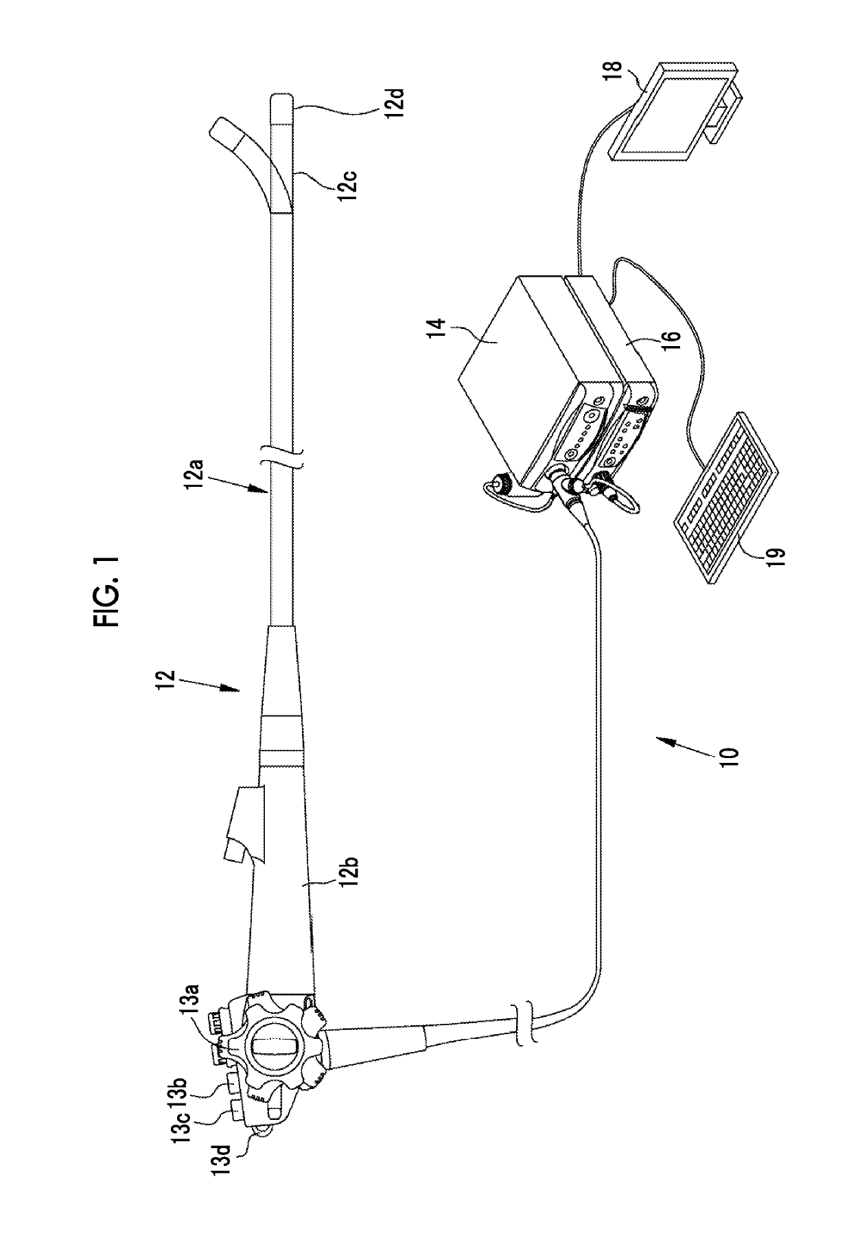
[0039]As illustrated in FIG. 1, an endoscope system 10 has an endoscope 12, a light source device 14, a processor device 16, a monitor 18 (display unit), and a console 19. The endoscope 12 is optically connected to the light source device 14, and is electrically connected to the processor device 16. The endoscope 12 has an insertion part 12a to be inserted into a subject, an operating part 12b provided at a proximal end portion of the insertion part 12a, and a bending part 12c and a distal end part 12d provided on a distal end side of the insertion part 12a. By operating an angle knob 13a of the operating part 12b, the bending part 12c makes a bending motion. The distal end part 12d is directed in a desired direction by this bending motion.

[0040]Additionally, the operating part 12b is provided with a still image acquisition unit 13b used for operating the acquisition of still images, a mode switching unit 13c used for operating the switching of observation modes, and a zooming opera...

second embodiment

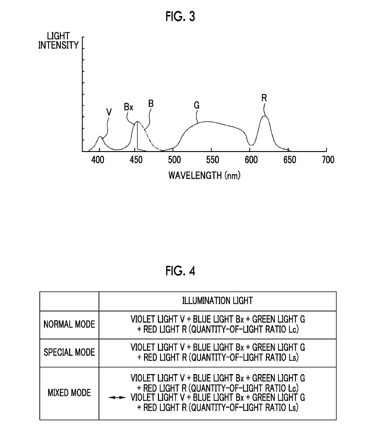
[0088]In the first embodiment, in the special mode, all the violet light V, the blue light Bx, the green light G, and the red light R are simultaneously emitted as the special mode illumination light, but in the second embodiment, as illustrated in FIG. 14, in the special mode, the violet light V and the blue light Bx are alternately emitted as the special mode illumination light. In the mixed mode, as the normal mode illumination light, the violet light V, the blue light Bx, the green light G, and the red light R are simultaneously emitted at the quantity-of-light ratio Lc, and thereafter, as the special mode illumination light, the violet light V and the blue light Bx are alternately emitted.

[0089]In the second embodiment, the special mode light emission condition corresponds to “alternately emitting the violet light V and the blue light Bx”. Further, in the second embodiment, a plurality of colors of light is simultaneously emitted for the normal mode illumination light, and a pl...

third embodiment

[0093]In a third embodiment, the observation target is illuminated using a laser light source and a fluorescent body instead of the four-color LEDs 20a to 20d illustrated in the first embodiment. Except for that, the third embodiment is the same as the first embodiment.

[0094]As illustrated in FIG. 15, in the endoscope system 100 of the third embodiment, the light source 20 of the light source device 14 is provided with a blue laser light source (written as “445LD”; LD represents the “laser diode”) 104 that emits blue laser light having a central wavelength of 445±10 nm and a blue-violet laser light source (written as “405LD”) 106 that emits blue-violet laser light having a central wavelength of 405±10 nm, instead of the four-color LEDs 20a to 20d. The light emission from semiconductor light-emitting elements of the respective light sources 104 and 106 are individually controlled by a light source control unit 108, and the quantity-of-light ratio of the emitted light of the blue lase...


PUM


Abstract

An endoscope system which can reduce visual discomfort even in a case where a normal image and a special image are alternately displayed, and a method of operating the endoscope system are provided. In a case where an observation target including a first structure is illuminated with first mode illumination light, a first mode display image obtained by imaging the observation target is acquired. In a case where the observation target is illuminated with second mode illumination light, a second mode display image obtained by imaging the observation target is acquired. A corrected image is obtained by correcting the first mode display image or the second mode display image such that a difference in a color and/or brightness of the first structure between the first mode display image and the second mode display image before the correction becomes small.

Description

CROSS-REFERENCE TO RELATED APPLICATIONS[0001]This application is a Continuation of PCT International Application No. PCT / JP2017 / 033637 filed on Sep. 19, 2017, which claims priority under 35 U.S.C § 119(a) to Patent Application No. 2016-195345 filed in Japan on Oct. 3, 2016, all of which are hereby expressly incorporated by reference into the present application.BACKGROUND OF THE INVENTION1. Field of the Invention[0002]The present invention relates to an endoscope system which displays a normal image of a natural color and a special image having high visibility of a vascular structure, and a method of operating the endoscope system.2. Description of the Related Art[0003]In a medical field, diagnosis using an endoscope system comprising a light source device, an endoscope, and a processor device has been performed widely. The endoscope system irradiates an observation target via the endoscope with illumination light emitted from the light source device, and the processor device genera...

Claims


Application Information

Patent Timeline
Patent Type & Authority Applications(United States)
IPC IPC(8): H04N5/235H04N5/225H04N9/73G06K9/62A61B1/04A61B1/00A61B1/06A61B1/07G06V10/143
CPCH04N5/2352H04N5/2256H04N9/735G06K9/6232A61B1/041A61B1/00009A61B1/0005A61B1/0669A61B1/07A61B1/0638A61B1/0684A61B1/00006H04N2005/2255G06K2209/05A61B1/0646G06V10/143G06V2201/034G06V2201/031A61B1/000094H04N23/555H04N23/56H04N23/88G06V2201/03G06F18/213H04N23/72
Inventor AOYAMA, TATSUYA
Owner FUJIFILM CORP
Why Eureka
Try Eureka