
A lens module grid lighting fixture

A lens module and lighting technology, applied in the field of lighting, can solve the problems of affecting the uniformity of light distribution of lamps, unable to achieve accurate light distribution, increasing the loss of luminous flux, etc., so as to reduce visual discomfort, reduce the loss of luminous flux, Glare reduction effect

Active Publication Date: 2021-06-15
CHANGCHUN CEDAR ELECTRONICS TECH CO LTD
View PDF10 Cites 0 Cited by
  • Summary
  • Abstract
  • Description
  • Claims
  • Application Information

AI Technical Summary

Problems solved by technology

However, the light source passes through the optical element and the grille module, which increases the loss of luminous flux and cannot achieve precise light distribution, resulting in uneven light distribution and affecting the uniformity of light distribution in the environment where the lamp is used

Method used


Image

  • A lens module grid lighting fixture
  • A lens module grid lighting fixture
  • A lens module grid lighting fixture

Examples


Embodiment 1

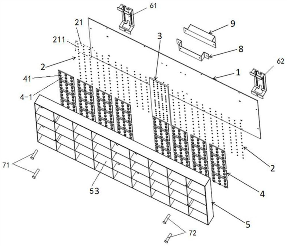
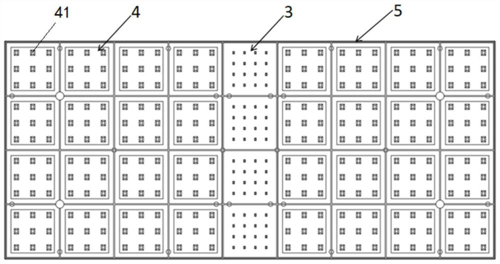
[0034] refer to Figure 1 to Figure 6 As shown, a preferred embodiment of the present invention is an eye protection lighting fixture, including: a rear cover 1 , a lens module 4 , a grille 5 , a hanging arm 61 , a hanging arm 62 , a power supply bracket 8 , and a power supply 9 . Such as figure 1 As shown, the rear cover 1 is a rear lampshade and circuit board; the front surface of the rear cover 1 includes a plurality of light emitting units 21 and a special light emitting area 3 . A plurality of light emitting units 21 constitute the white light emitting area 2; the lens module 4 is installed in front of the back cover 1; the grille 5 is fixedly connected with the back cover 1, and has functions of controlling glare and concentrating light. A pair of screw posts 71 pass through the screw holes 53 of the grille 5 and the screw holes of the rear cover 1 and are fixedly connected with the hanging arm 61, and the other pair of screw posts 72 pass through the screw holes 52 of ...

Embodiment 2

[0038] refer to Figure 7 to Figure 11As shown, the preferred embodiment 2 of the present invention includes: a rear cover 1 , a lens module 4 , a grille 5 , hanging arms 61 , 62 , two power supply brackets 8 , a power supply 9 , buckles 11 , and screw holes 12 . The back cover 1 is a rear lampshade and a circuit board, and the front surface of the back cover 1 includes a plurality of light emitting units 21; each light emitting unit 21 contains a plurality of single LED white light sources and LED special light sources welded and fixed on the front surface of the back cover 1 The lens module 4 includes a plurality of module units 4-1; the grid 5 is formed by vertically crossed grid bars; the grid 53 of the light emitting unit 21, the module unit 4-1 and the grid 5 One-to-one correspondence of positions. The single LED white light source 211 and the LED special light source in each light emitting unit 21 correspond to the position of the lens unit 41 in the module unit 4-1 on...


PUM

PropertyMeasurementUnit
wavelengthaaaaaaaaaa

Abstract

The invention relates to a lens module grid lighting lamp, the back cover of the lamp is a rear lampshade and a circuit board; each light-emitting unit includes an LED white light source composed of multiple single LED white light sources fixed on the front surface of the back cover The lens module is installed in front of the back cover, and each single LED white light source corresponds to the position of the lens unit on the lens module; the grille is located in front of the lens module and is fixedly connected with the back cover; the light emitting unit, The module unit corresponds to the grid position of the grille one by one; the power supply is fixed on the rear cover through the power supply bracket. The invention can effectively reduce luminous flux loss, increase illuminance, and control glare, and has simple structure and low cost, and can be applied to classroom lighting and lighting in workplaces such as factories, homes, and offices.

Description

Technical field: [0001] The invention belongs to the technical field of lighting, and relates to a lens module grid lighting lamp, in particular to a classroom module lamp with high light efficiency and anti-glare. Background technique: [0002] The incidence of myopia in children and adolescents in my country is very serious, and it has become a public health problem that seriously affects public health and quality of life. There are many causes of myopia. According to the current theoretical and experimental studies by many researchers, the light environment has a great influence on myopia. Children and adolescents spend most of their time in school. It is of great significance to reduce the myopia rate of young people and improve the national health level. [0003] The eye protection lighting lamps that are currently being sold in the industry include lampshades, light-emitting elements, grids and power supply devices. The lampshade is a cover with an opening, and the li...

Claims


Application Information

Patent Timeline
Patent Type & Authority Patents(China)
IPC IPC(8): F21K9/69F21K9/60F21V13/02F21V11/06F21V5/04F21W131/402F21Y115/10
CPCF21V5/04F21V11/06F21V13/02F21W2131/402F21K9/60F21K9/69F21Y2115/10
Inventor 王瑞光黄耀伟阮程丁强汪洋孙铭泽陈磊邵长勇
Owner CHANGCHUN CEDAR ELECTRONICS TECH CO LTD
Learn More