System for camera control in robotic and laparoscopic surgery

a robotic and laparoscopic surgery and camera control technology, applied in the field of laparoscopic surgery, can solve the problems of increased operating time, poor human-in-the-loop interaction with the robotic laparoscope holder, and abrupt movement of the operating field on the display

Pending Publication Date: 2019-07-25
QATOR FOUND FOR EDUCATION SCI & COMMUNITY DEV +1
View PDF0 Cites 6 Cited by
  • Summary
  • Abstract
  • Description
  • Claims
  • Application Information

AI Technical Summary

Benefits of technology

[0005]The system for camera control in robotic and laparoscopic surgery includes a head tracking system for tracking movements of an operator's head during laparoscopic surgery, a robotic laparoscope holder operatively engaged to a laparoscope, an interface workstation having a processor and inputs connecting the sensor signal and the servo control system signals to the processor, and a clutch switch connected to the processor for activating and inactivating the interface workstation. The head tracking system includes at least one optical marker to be worn on the operator's head and an optical tracker for detecting movement of the at least one optical marker and transmitting a corresponding sensor signal. The laparoscope includes an articulating distal portion, a tip, and a camera disposed at the tip.
[0006]These and other features of the present invention will become readily apparent upon further review of the following specification and drawings.

Problems solved by technology

Since the medical professional does not have direct control over the visualization of the operative field, miscommunications between the surgeon and the assistant may occur, leading to complications and increased operating time.
Apart from miscommunication, the assistant is subject to fatigue, distractions, and natural hand-tremors that may result in abrupt movement of the operating field on the display.
This can result in poor human-in-the-loop interaction with the robotic laparoscope holder.
Further, the incision point acts as a fulcrum for the laparoscope, thereby causing scaling and inversion of movements, as well as making the maneuvering of the camera disposed at the distal end of the laparoscope challenging, especially in the case of articulated and angulated laparoscopes.

Method used


Image

  • System for camera control in robotic and laparoscopic surgery
  • System for camera control in robotic and laparoscopic surgery
  • System for camera control in robotic and laparoscopic surgery

Examples


Embodiment Construction

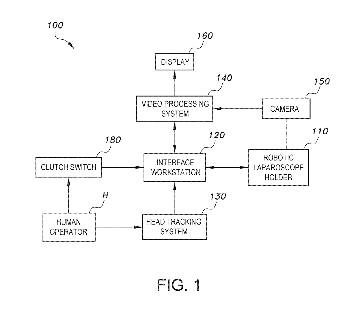
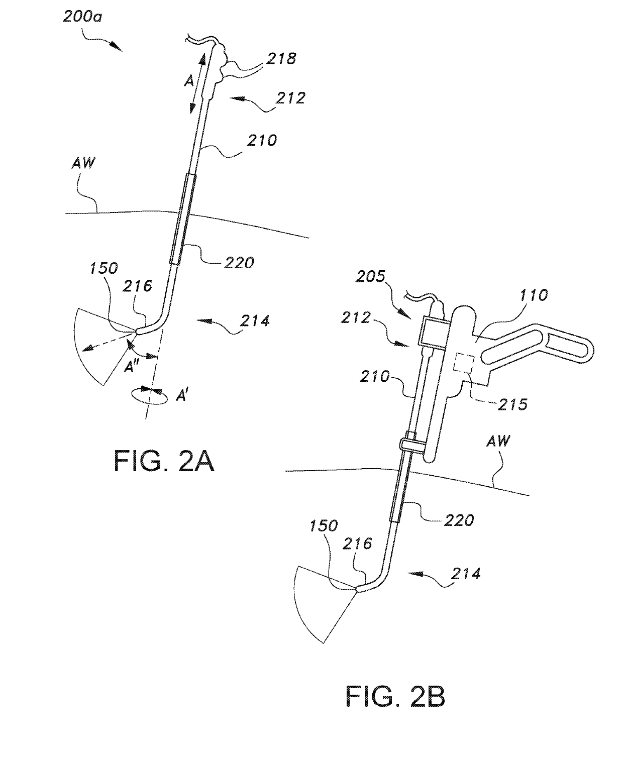
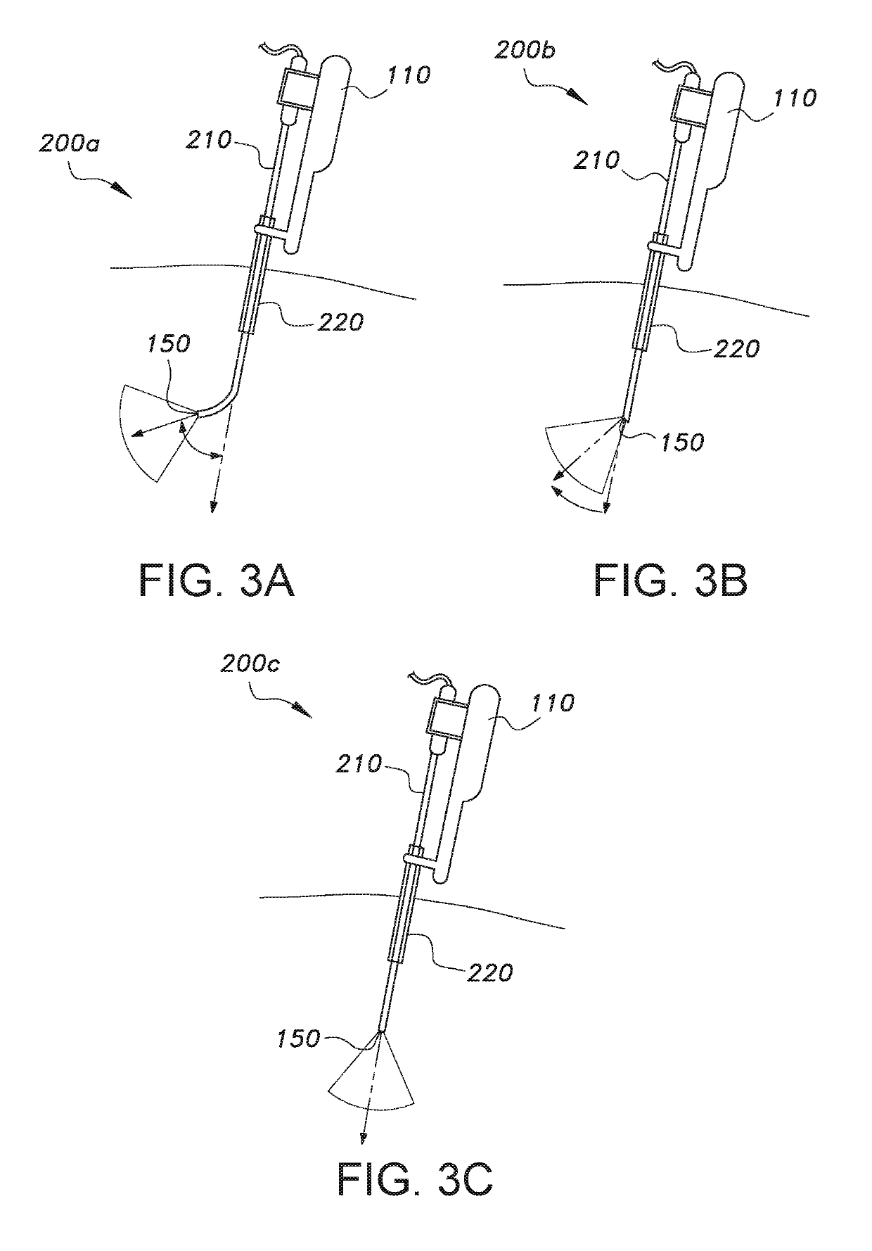
[0044]Referring to FIGS. 1 through 9C, a system for camera control in robotic and laparoscopic surgery 100 is generally illustrated. The system 100 is configured to track movement of the head of a human operator H (e.g., surgeon) during a laparoscopic surgical procedure and move the camera 150 in a direction that corresponds to the movement of the head. The system 100 can be a software module running on an interface workstation 120. The system 100 includes a robotic laparoscope holder 110, a laparoscope, such as an articulated laparoscope 200a (FIG. 3A), an angulated laparoscope 200b (FIG. 3B) or a zero degree laparoscope 200c (FIG. 3C), selectively connected to the laparoscope holder, such as via a laparoscope adapter 205, a head tracking system 130 in communication with the interface workstation, a video processing system in communication with the interface workstation 120, a display 160 in communication with the video processing system 140, and a clutch in communication with the ...


PUM


Abstract

The system for camera control in robotic and laparoscopic surgery (100) includes a head tracking system (130) for tracking movements of an operator's head during laparoscopic surgery, a robotic laparoscope holder (110) operatively engaged to a laparoscope (200), an interface workstation (120) having a processor (540) and inputs connecting the sensor signal and the servo control system (515) signals to the processor (540), and a clutch switch (180) connected to the processor (540) for activating and inactivating the interface workstation (120). The head tracking system (130) includes at least one optical marker (415) to be worn on the operator's head and an optical tracker (410) for detecting movement of the at least one optical marker (415) and transmitting a corresponding sensor signal. The laparoscope includes an articulating distal portion (214), a tip (216), and a camera (150) disposed at the tip (150).

Description

TECHNICAL FIELD[0001]The present invention relates to a system for laparoscopic surgery, and particularly to a system for controlling a camera attached to a laparoscope by head movements of the surgeon.BACKGROUND ART[0002]Typically in a classical laparoscopic surgery setting, a medical professional operates on a tissue using instruments inserted through small incisions. The operating field inside a patient's body is visualized using a camera attached to a laparoscope. During a laparoscopic procedure, both hands of the medical professional are usually occupied with laparoscopic instruments. As such, an experienced assistant is required to maneuver the laparoscope and continuously provide necessary visualization of the operating field to the surgeon. Since the medical professional does not have direct control over the visualization of the operative field, miscommunications between the surgeon and the assistant may occur, leading to complications and increased operating time. Apart fro...

Claims


Application Information

Patent Timeline
Patent Type & Authority Applications(United States)
IPC IPC(8): A61B34/30A61B90/00A61B34/20A61B34/00
CPCA61B34/30A61B90/361A61B90/37A61B2017/00216A61B34/74A61B2034/2055A61B2034/302A61B34/20A61B2090/368A61B2090/502
Inventor NAVKAR, NIKHIL V.ABINAHED, JULIEN ANTOINEBALAKRISHNAN, SHIDINAL-ANSARI, ABDULLA
Owner QATOR FOUND FOR EDUCATION SCI & COMMUNITY DEV
Why Eureka
Try Eureka