Prosthesis for a fractured long bone

a long bone and prosthesis technology, applied in the field of prosthesis for fractured long bones, can solve the problems of requiring high dexterity for surgeons to attach the tuberosities by suturing, and the sutures sometimes do not prevent the tuberosities, so as to achieve easy and reliable securing of the exterior par

Active Publication Date: 2019-08-01
TORNIER SA SAINT ISMIER
View PDF0 Cites 8 Cited by
  • Summary
  • Abstract
  • Description
  • Claims
  • Application Information

AI Technical Summary

Benefits of technology

[0071]In this invention, the implant is distinct from the stem part, so that the surgeon may choose in situ whether the stem part should be provided with the exterior part or not depending on the situation. Thus, the stem part may be used without the implant. Attaching the exterior part to the stem part through the gap allows an easy and reliable securing of the exterior part thereto. One or more epiphyseal fragment(s) may be secured to the exterior part. The exterior part may structurally reinforce the fragment secured thereto. The fragment may be backed by the exterior part to which said fragment is attached. Thus, even thin or fragile fragments may be reattached to the stem part. Otherwise, one or more of the exterior parts may replace one of the fragments, not reintroduced into the patient. The presence of the exterior part(s) allows, for a single stem part, to obtain patient-specific or at least desired peripheral shape of the prosthesis, so that the surgeon may modify and adapt the prosthesis to any situation, by providing the appropriate exterior part.

Problems solved by technology

However, the sutures sometimes do not prevent tuberosities to migrate after surgery because of the movements of the patient, all the more as muscles are usually anchored to said tuberosities.
Also, attaching the tuberosities by suturing requires a high dexterity for the surgeon.

Method used


Image

  • Prosthesis for a fractured long bone
  • Prosthesis for a fractured long bone
  • Prosthesis for a fractured long bone

Examples


Embodiment Construction

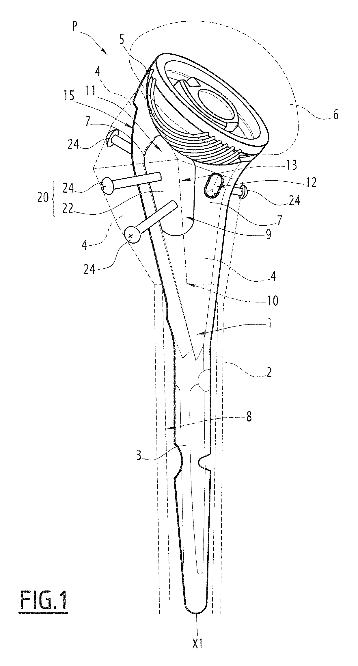
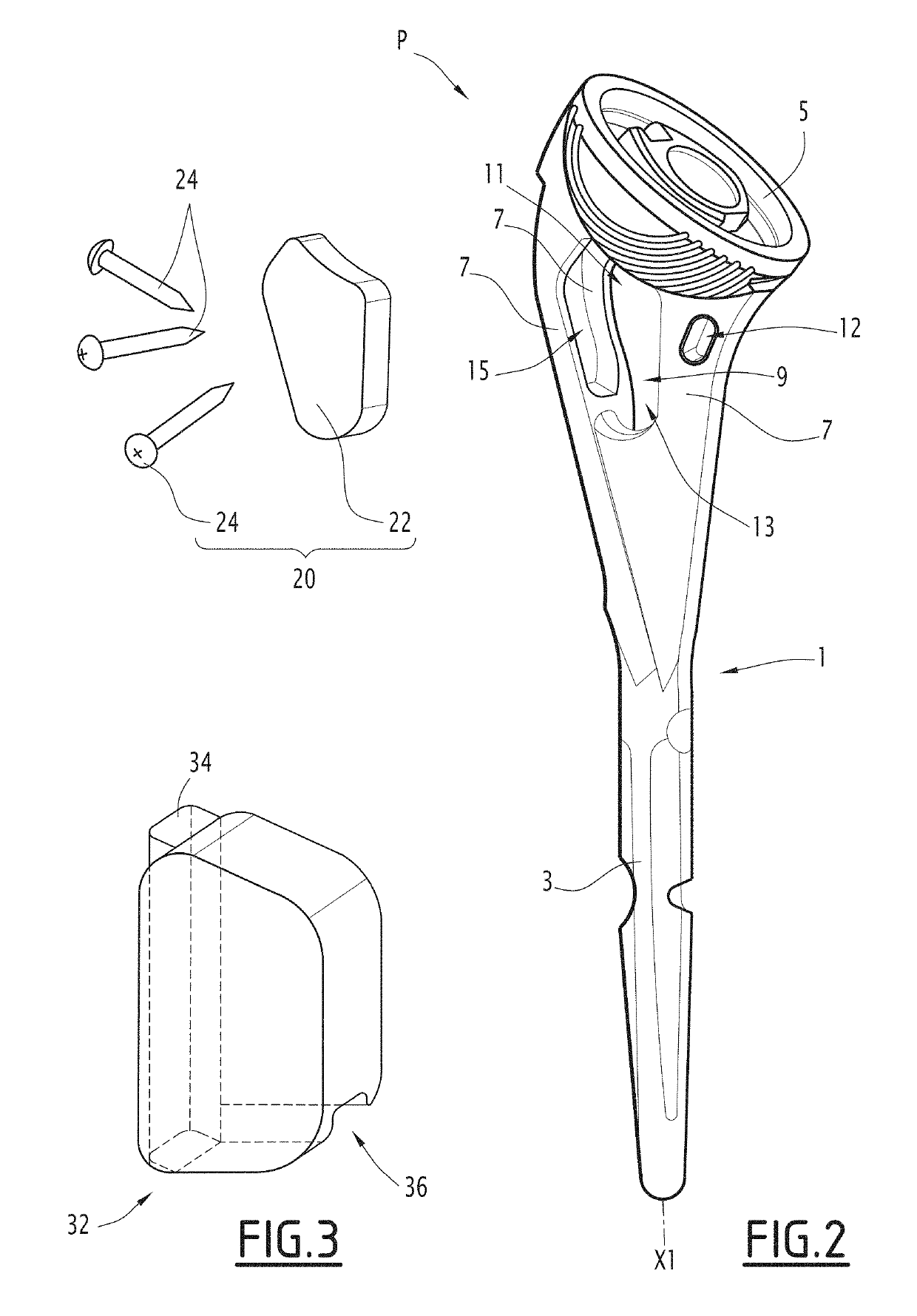
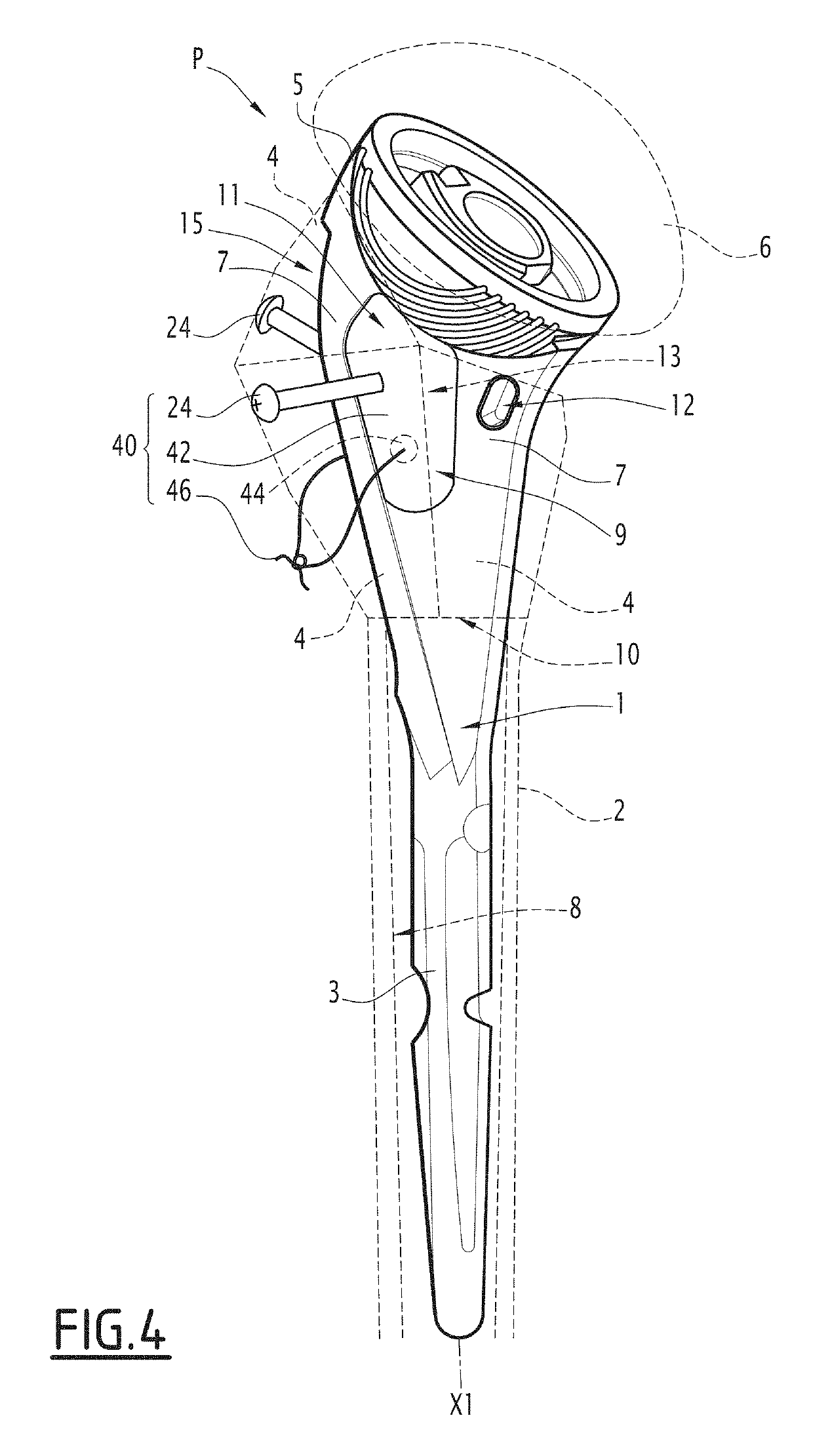
[0117]The prosthesis P of FIGS. 1-18 are prosthesis P for a fractured long bone, in particular a fractured humerus. Thus the prosthesis P of FIGS. 1-18 are designed for shoulder arthroplasty.

[0118]As illustrated schematically in dashed lines on FIG. 1, the fractured long bone comprises:[0119]a diaphyseal fragment 2, of generally tubular shape, comprising a medullary cavity 8, the cavity 8 being opened at a proximal end 10 of the fragment 2, where the bone is fractured, and[0120]three epiphyseal fragments 4, or tuberosities, to be positioned at the end 10 of the fragment 2 for reconstructing the original bone.

[0121]Depending on the fracture type, more or less than three fragments 4 may be formed from the initial tuberosities of the patient's bone. Muscles of the patient may originally be anchored to all or some of the fragments 4.

[0122]The initial long bone may have comprised a head for forming a joint with another bone, in this case a humeral head for forming the shoulder joint with...


PUM

PropertyMeasurementUnit
sizeaaaaaaaaaa
metallicaaaaaaaaaa
durableaaaaaaaaaa

Abstract

The invention concerns a prosthesis comprising: a stem part comprising: a rod, configured for being inserted into a medullary cavity of a diaphyseal fragment of a fractured long bone, for securing the stem part to the diaphyseal fragment, and an epiphyseal end, fixedly secured to the rod by means of at least one linker leg of the stem part, so that a gap is formed between the epiphyseal end and the rod along said at least one linker leg; and an implant distinct from the stem part and comprising: an internal part located at least partially within the gap, and at least one fastener for fastening epiphyseal fragments of the fractured long bone to the stem part, said at least one fastener being secured to the internal part.

Description

INCORPORATION BY REFERENCE TO ANY PRIORITY APPLICATIONS[0001]Any and all applications for which a foreign or domestic priority claim is identified in the Application Data Sheet as filed with the present application are hereby incorporated by reference under 37 C.F.R. § 1.57.BACKGROUND OF THE INVENTIONField of the Invention[0002]The invention relates to a prosthesis for a fractured long bone.[0003]The invention relates to the domain of joint arthroplasty, preferably shoulder arthroplasty, alternatively to hip arthroplasty. The invention preferably applies to human patients, but could also be applied to animal patients.Description of the Related Art[0004]US2004 / 0230311 A1 discloses a shoulder prosthesis to be used to replace the upper humerus in certain fracture types. This known prosthesis comprises a stem to be inserted in the canal of the humerus, an intermediary part reduced to a medial pillar and a head which is a hollow and generally spherical cap. The head of the prosthesis is ...

Claims


Application Information

Patent Timeline
Patent Type & Authority Applications(United States)
IPC IPC(8): A61F2/40A61F2/28A61F2/30
CPCA61F2/4059A61F2/28A61F2/4014A61F2/30734A61B17/86A61F2002/2853A61F2210/0014A61F2002/4631A61F2310/00023A61F2002/30332A61F2002/30092A61F2/4003A61F2002/4062A61F2/32A61F2/36A61F2210/0004A61F2220/0016A61F2220/0041A61L27/06A61L27/12A61L27/16A61L27/18A61L27/50A61L27/56A61L27/58A61L2430/24C08L67/04C08L61/16C08L23/06A61F2002/2835A61F2002/30433A61F2002/30593A61F2002/30827A61F2002/30879A61F2002/4066
Inventor BOILEAU, PASCALCARDON, JEAN-EMMANUELCLAIZERGUES, BERTRANDCOULANGE, VINCENTDASSONVILLE, BENJAMINGABORIT, VINCENT
Owner TORNIER SA SAINT ISMIER
Why Eureka
Try Eureka