
Residual oil drainage system and related method for replacing an oil filter of an engine

a technology of residual oil and drainage system, which is applied in the direction of lubricant mounting/connection, lubrication elements, pressure lubrication, etc., can solve the problems of residual oil trapped inside and around the filter mounting location of the engine, and achieve the effect of reducing or eliminating the spillage and leakage of residual engine oil

Active Publication Date: 2019-08-01
KOHLER CO
View PDF5 Cites 3 Cited by
  • Summary
  • Abstract
  • Description
  • Claims
  • Application Information

AI Technical Summary

Benefits of technology

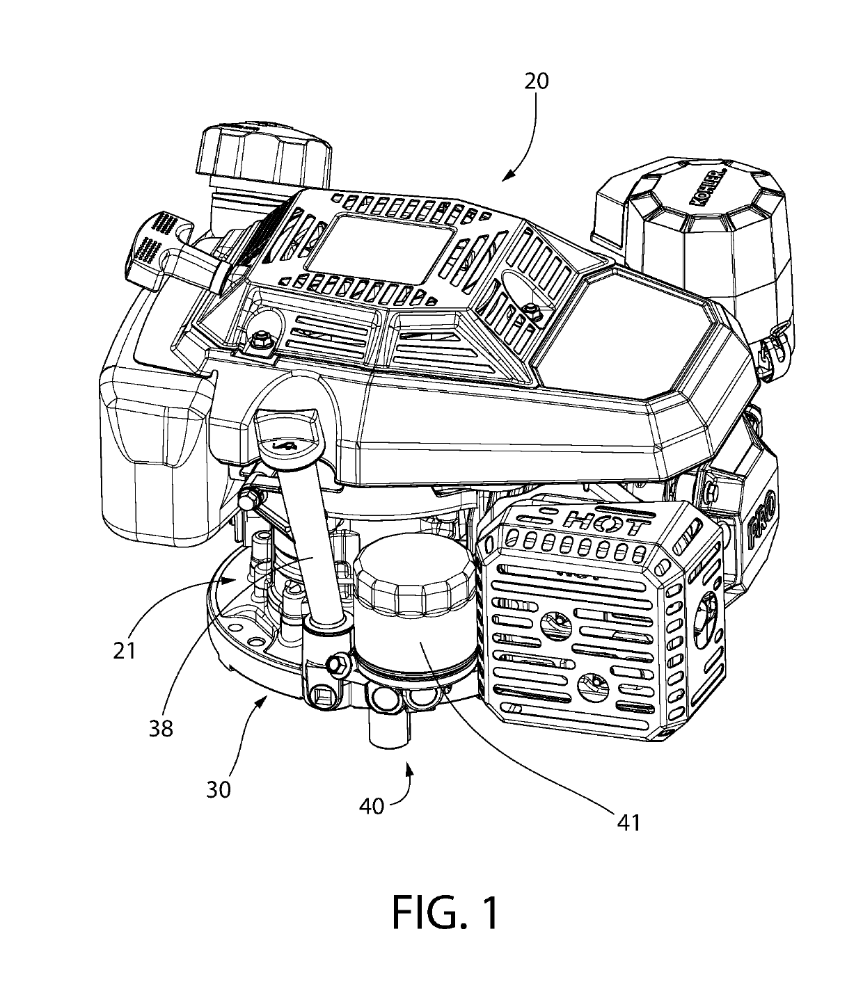
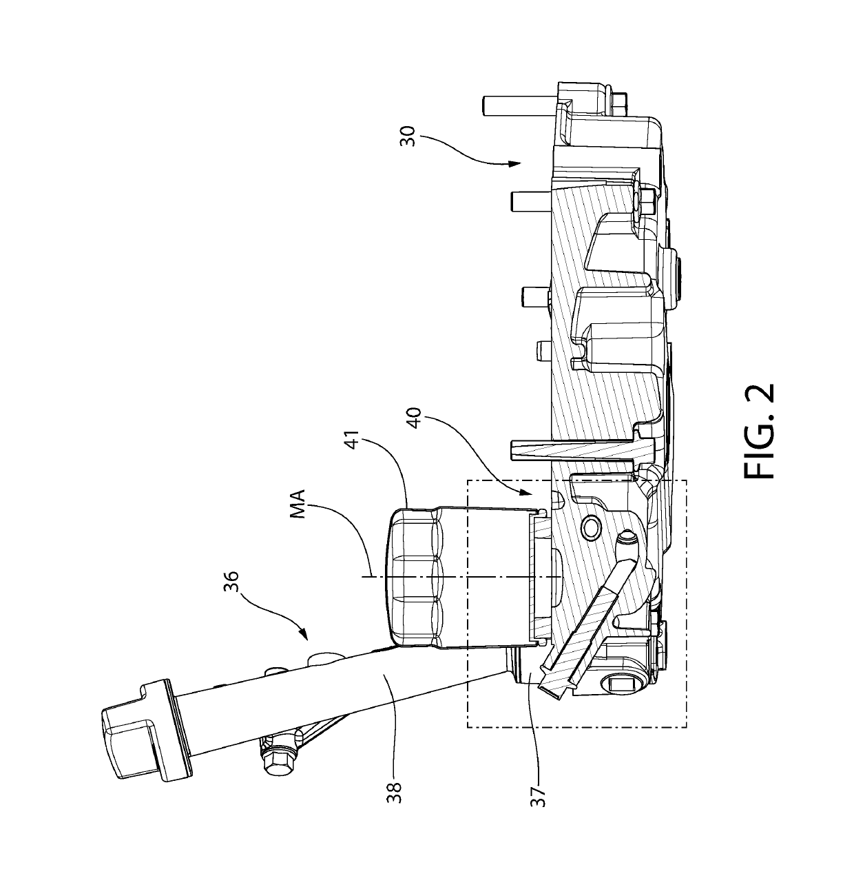
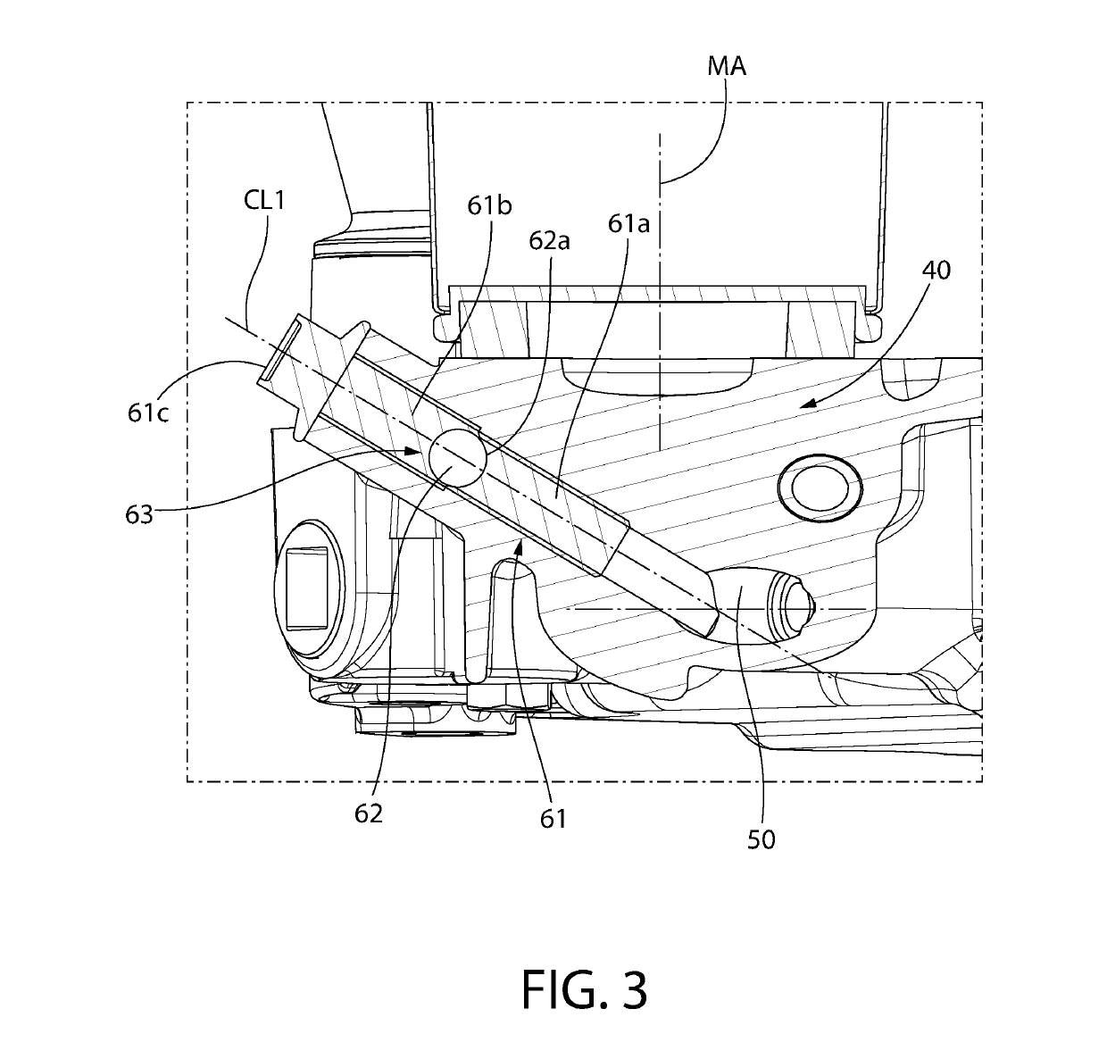
The present invention is a drainage system and method for removing and replacing an oil filter in an internal combustion engine. The system is designed to reduce or eliminate spilling and leaking of residual engine oil during the process. The system includes a first drainage conduit to collect and return oil from the engine back to the oil reservoir, and a second drainage conduit to supply oil to the filter. The system is operated before replacing the filter to remove residual oil from the normal oil flow conduits and associated surfaces to avoid spills. The system has the advantage of allowing for a cleaner oil filter replacement and the engine oil to be drained from only one location. It is simple in design and easy to use, and it eliminates two potential sources of spillage when the filter is removed.

Problems solved by technology

When replacing some oil filters, residual oil trapped inside and around the filter mounting location on the engine may spill requiring either separate catch pan and / or cumbersome cleanup steps.

Method used


Image

  • Residual oil drainage system and related method for replacing an oil filter of an engine
  • Residual oil drainage system and related method for replacing an oil filter of an engine
  • Residual oil drainage system and related method for replacing an oil filter of an engine

Examples


Embodiment Construction

[0029]The features and benefits of the invention are illustrated and described herein by reference to example (“exemplary”) embodiments. This description of example embodiments is intended to be read in connection with the accompanying drawings, which are to be considered part of the entire written description. Accordingly, the disclosure expressly should not be limited to such embodiments illustrating some possible non-limiting combination of features that may exist alone or in other combinations of features.

[0030]In the description of embodiments disclosed herein, any reference to direction or orientation is merely intended for convenience of description and is not intended in any way to limit the scope of the present invention. Relative terms such as “lower,”“upper,”“horizontal,”“vertical,”, “above,”“below,”“up,”“down,”“top” and “bottom” as well as derivative thereof (e.g., “horizontally,”“downwardly,”“upwardly,” etc.) should be construed to refer to the orientation as then descr...


PUM


Abstract

A residual oil drainage system for use in replacement of the oil filter of an internal combustion engine is disclosed. The drainage system may include first and second drainage conduits disposed in the oil pan of the engine. The drainage conduits may be fluidly interconnected and coupled to portions of the oil inlet and outlet flow conduits which normally convey oil to and from the oil filter. A flow control device is movable to either open or close the drainage flowpath in the system. In use with an open flowpath and engine off, residual oil captured by the first and second drainage conduits flows through the drainage system and is returned to the oil reservoir in the oil pan via gravity. In one configuration, the drainage conduits are formed internally and directly within the body of the structure of the oil pan.

Description

CROSS-REFERENCE TO RELATED APPLICATIONS[0001]The present application claims the benefit of U.S. Provisional Application No. 62 / 622,550 filed Jan. 26, 2018; the entirety of which is incorporated herein by reference.BACKGROUND OF THE DISCLOSURE[0002]The present disclosure generally relates to oil lubrication systems for internal combustion engines, and more particularly to a drainage system and method for capturing residual oil associated with oil filter replacement.[0003]Oil lubrication systems for internal combustions engines distribute oil to moving engine parts for reducing friction-related wear and cooling. Such systems may generally include an oil sump or pan, a pump, and a filter. The oil filter contains filter media which removes sediment and debris collected by the circulating oil to prevent etching of wear surfaces between intermeshing engine parts. Both the oil and filter require periodic replacement. When replacing some oil filters, residual oil trapped inside and around t...

Claims


Application Information

Patent Timeline
IPC IPC(8): F01M11/04F01M11/03F01M11/02F16N31/00
CPCF01M11/0458F01M11/03F01M11/0408F01M11/02F16N31/002F01M2011/035F01M2011/0425F01M2011/031
Inventor VANDRIE, ERIC MITCHELLHUIBREGTSE, MARK
Owner KOHLER CO
Learn More