
Electrically-driven vehicle and control method for electrically-driven vehicle

a technology of electric vehicles and control methods, applied in secondary cells, battery servicing/maintenance, instruments, etc., can solve problems such as power deficiency (depletion of power storage energy), power deficiency actually occurring, and possibly and erroneously determined power deficiency, etc., to suppress the cause of erroneous determination of power deficiency and suppress the effect of erroneous determination

Active Publication Date: 2019-08-01
TOYOTA JIDOSHA KK
View PDF0 Cites 0 Cited by
  • Summary
  • Abstract
  • Description
  • Claims
  • Application Information

AI Technical Summary

Benefits of technology

The present disclosure provides an electrically-driven vehicle and control method that can prevent incorrect detection of power deficiency. By adding the output power of the power storage device to the condition for stopping the electrically-driven vehicle, unnecessary processing can be avoided. Additionally, by minimizing the difference between the actual power output and the upper limit value, the cause of incorrect power deficiency detection can be reduced. In summary, the disclosed technology can prevent incorrect detection of power deficiency and increase the reliability of the electrically-driven vehicle.

Problems solved by technology

In the case where such an output power upper limit value (Wout) is calculated by using the SOC and an estimated SOC value has an error, power deficiency (depletion of power storage energy) is possibly and erroneously determined in a situation where the SOC is low.
In the case where it is determined that the power storage device still can output the power while the output power upper limit value is decreased in the situation where the SOC is low, the power deficiency actually occurs.
Despite a fact that the power storage device cannot actually output the power allowing travel of the electrically-driven vehicle due to power deficiency, the output power upper limit value indicates that the power storage device still can output the power allowing the travel of the electrically-driven vehicle.
As a result, an erroneous determination of the power deficiency is made.

Method used


Image

  • Electrically-driven vehicle and control method for electrically-driven vehicle
  • Electrically-driven vehicle and control method for electrically-driven vehicle
  • Electrically-driven vehicle and control method for electrically-driven vehicle

Examples


Embodiment Construction

[0025]A detailed description will hereinafter be made on an embodiment of the present disclosure with reference to the drawings. Note that the same or corresponding portions in the drawings are denoted by the same reference numerals and the description thereon will not be repeated.

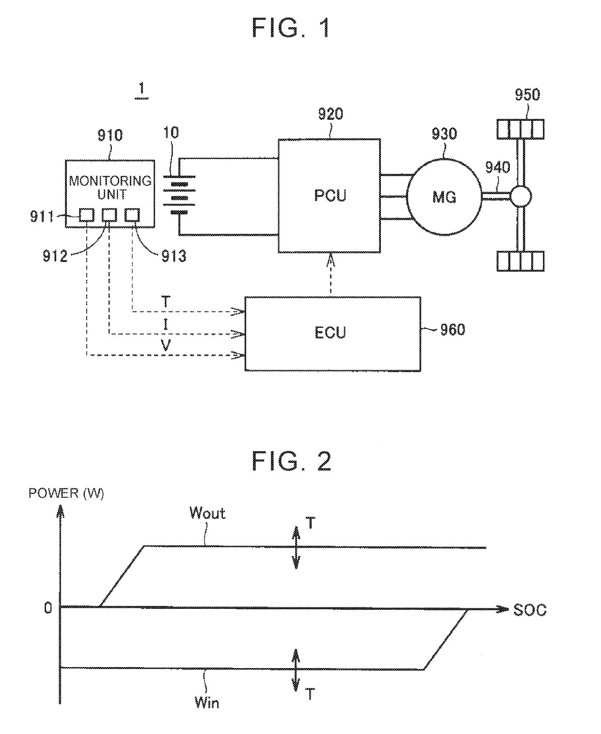
[0026]FIG. 1 is a schematic configuration diagram of an electrically-driven vehicle according to an embodiment of the present disclosure. With reference to FIG. 1, an electrically-driven vehicle 1 includes a battery pack 10, a monitoring unit 910, a power control unit (hereinafter referred to as a “PCU”) 920, a motor generator (hereinafter referred to as a “MG”) 930, a drive shaft 940, drive wheels 950, and an electronic control unit (hereinafter referred to as an “ECU”) 960.

[0027]The battery pack 10 is configured to include plural secondary battery cells (hereinafter also simply referred to as “cells”). Each of the cells is configured as a lithium-ion battery or a nickel-metal hydride battery, for example...


PUM

PropertyMeasurementUnit
stores poweraaaaaaaaaa
voltageaaaaaaaaaa
output poweraaaaaaaaaa

Abstract

An electrically-driven vehicle includes a power storage device that stores power to be supplied to a motor, and a controller that controls output of the power storage device. The controller estimates a SOC of the power storage device. The controller detects output power of the power storage device and calculates an output power upper limit value of the power storage device by using the SOC when a voltage of the power storage device reaches a lower limit voltage during discharge of the power storage device. The controller stops the electrically-driven vehicle in the case where the detected output power is lower than the output power upper limit value.

Description

INCORPORATION BY REFERENCE[0001]The disclosure of Japanese Patent Application No. 2018-012404 filed on Jan. 29, 2018 including the specification, drawings and abstract is incorporated herein by reference in its entirety.BACKGROUND1. Technical Field[0002]The present disclosure relates to an electrically-driven vehicle and a control method for an electrically-driven vehicle and, in particular, to an output control technique of a power storage device that stores electric power to be supplied to a motor for travelling.2. Description of Related Art[0003]A travelable distance calculation system for an electrically-driven vehicle that travels by using output of a motor has been disclosed in Japanese Patent Application Publication No. 2015-139346 (JP 2015-139346 A). In order to calculate a travelable distance, this system estimates a state of charge (SOC) of a battery (a power storage device) and calculates the travelable distance from the estimated SOC. A SOC-OCV (an open circuit voltage) ...

Claims


Application Information

Patent Timeline
Patent Type & Authority Applications(United States)
IPC IPC(8): G01R31/3842B60W10/08G01R19/165G01R31/389G01R31/36H01M10/48
CPCG01R31/3842B60W10/08G01R19/16542G01R31/389G01R31/3646H01M10/486B60L3/00H01M2220/20H01M10/44H01M10/425H01M2010/4271Y02T90/14Y02T10/7072Y02E60/10
Inventor YOSHIDA, HIROSHI
Owner TOYOTA JIDOSHA KK
Features
  • Generate Ideas
  • Intellectual Property
  • Life Sciences
  • Materials
  • Tech Scout
  • Unparalleled Data Quality
  • Higher Quality Content
  • 60% Fewer Hallucinations
Learn More