
Redox flow battery pipe, method for manufacturing redox flow battery pipe, pipe unit, and redox flow battery

Active Publication Date: 2019-08-01
SUMITOMO ELECTRIC IND LTD
View PDF4 Cites 0 Cited by
  • Summary
  • Abstract
  • Description
  • Claims
  • Application Information

AI Technical Summary

Benefits of technology

The redox flow battery pipe and the pipe unit have low risk of liquid leakage and can be made compact. The method of manufacturing the redox flow battery pipe is stable and accurate. The redox flow battery reduces the risk of liquid leakage of the pipe and saves installation space.

Problems solved by technology

Accordingly, it is expected that when such power generation using natural energy is introduced on a large scale, problems, such as difficulties in maintaining frequencies and voltages, may occur during the operation of power systems.

Method used


Image

  • Redox flow battery pipe, method for manufacturing redox flow battery pipe, pipe unit, and redox flow battery
  • Redox flow battery pipe, method for manufacturing redox flow battery pipe, pipe unit, and redox flow battery
  • Redox flow battery pipe, method for manufacturing redox flow battery pipe, pipe unit, and redox flow battery

Examples


Embodiment Construction

[0038][Technical Problem]

[0039]In general, a large-capacity RF battery includes a plurality of battery elements (a cell stack) and is configured so that a pipe through which an electrolyte flows is branched between a tank and each of the battery elements so as to transport the electrolyte between the single tank and the plurality of battery elements. In this case, a pipe (may be referred to as a “pipe unit”) that includes a trunk pipe connected to the tank side and a plurality of branch pipes that branch off from the trunk pipe and are connected to the corresponding battery element side is used as the pipe that forms an electrolyte flow path of the RF battery. The pipes used in an RF battery are formed of a resin that does not react with electrolytes, typically, a polyvinyl chloride resin (PVC) because the pipes come in direct contact with the electrolytes.

[0040]When the above pipe that includes a trunk pipe and branch pipes is used for the electrolyte flow path of an RF battery, a ...


PUM

PropertyMeasurementUnit
Thicknessaaaaaaaaaa
Thicknessaaaaaaaaaa
Diameteraaaaaaaaaa

Abstract

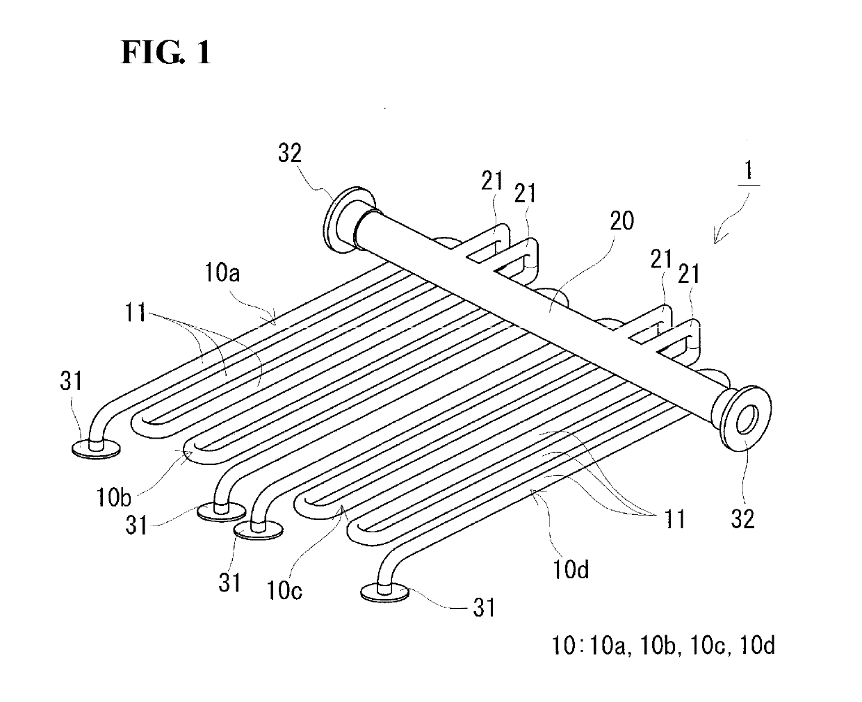
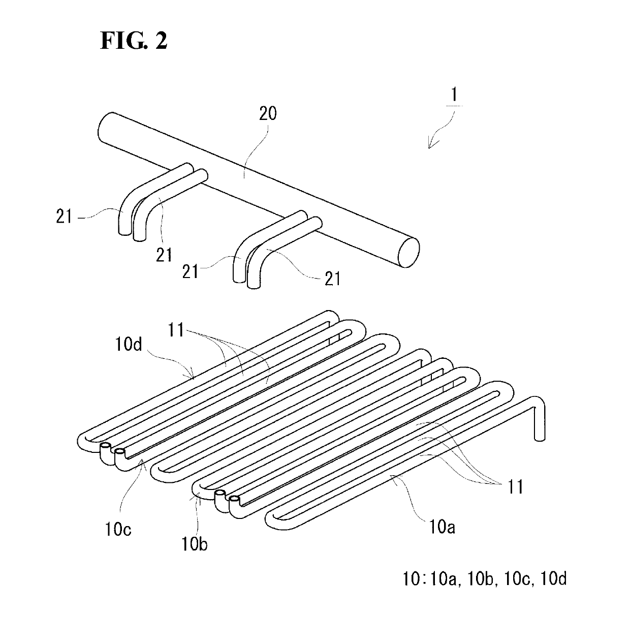
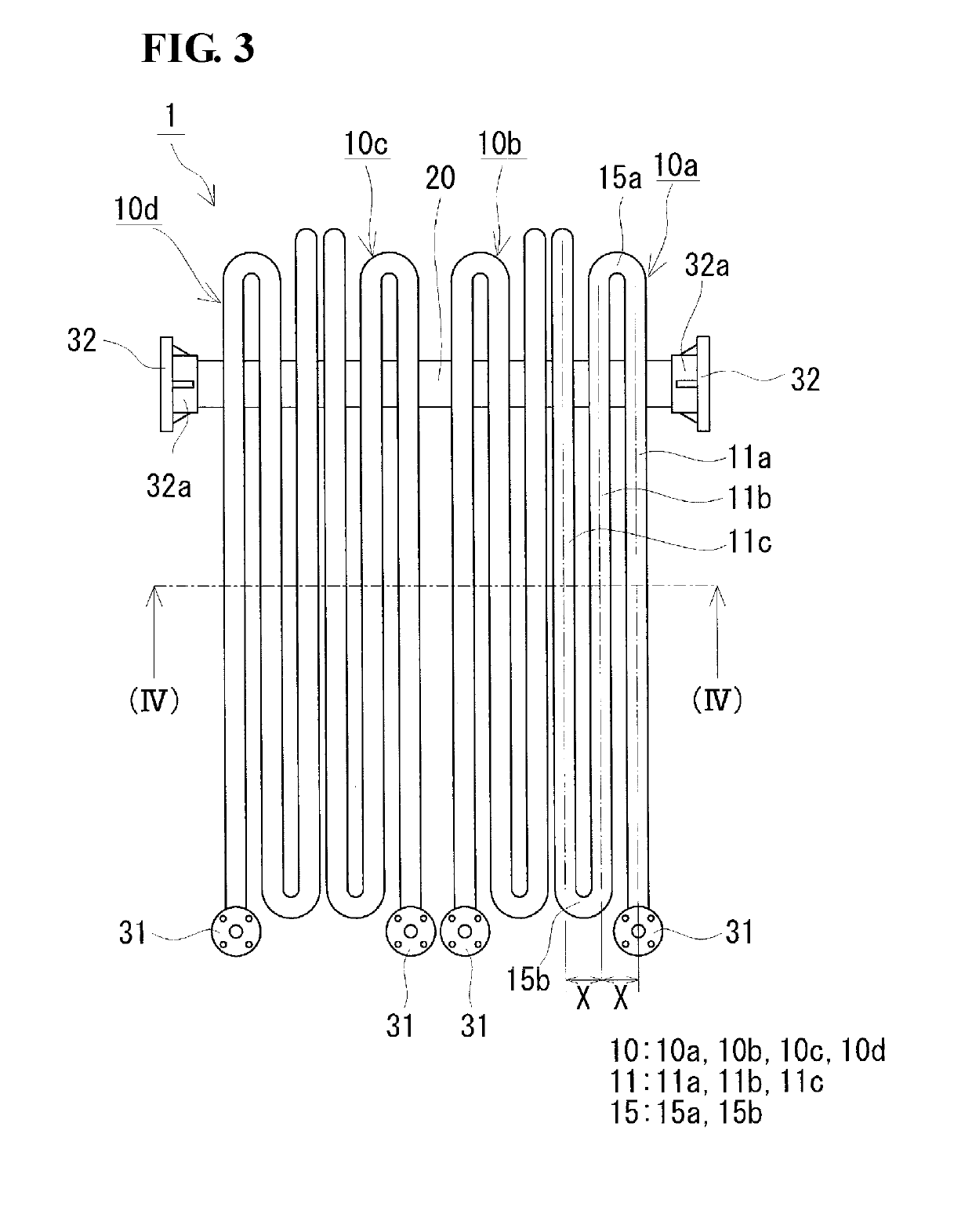
A redox flow battery pipe which is disposed between a tank that stores an electrolyte and a battery element and through which the electrolyte flows includes a plurality of parallel portions arranged in parallel and a plurality of bent portions connecting the parallel portions adjacent to each other. The pipe includes a meandering portion in which the parallel portions and the bent portions are integrally molded so as to be alternately connected. A ratio of a center-to-center distance X to an outer diameter D satisfies 1.2 or more and 2.5 or less where D represents an outer diameter and X represents a distance between centers of the parallel portions adjacent to each other.

Description

TECHNICAL FIELD[0001]The present invention relates to a redox flow battery pipe, a method for manufacturing a redox flow battery pipe, a pipe unit, and a redox flow battery.[0002]The present application claims priority from Japanese Patent Application No. 2016-104716 filed on May 25, 2016, and the entire contents of the Japanese patent application are incorporated herein by reference.BACKGROUND ART[0003]In recent years, in order to cope with global warming, introduction of power generation using natural energy (so-called renewable energy), such as solar photovoltaic power generation or wind power generation, has been promoted worldwide. The output of such power generation depends on natural conditions, such as weather. Accordingly, it is expected that when such power generation using natural energy is introduced on a large scale, problems, such as difficulties in maintaining frequencies and voltages, may occur during the operation of power systems. As a countermeasure for such probl...

Claims


Application Information

Patent Timeline
IPC IPC(8): H01M8/18H01M8/04276H01M8/04082
CPCH01M8/188H01M8/04276H01M8/04201Y02E60/50Y02P70/50H01M8/04216B29C39/08H01M8/18H01M8/04
Inventor ASANUMA, KENTAROIKEUCHI, ATSUO
Owner SUMITOMO ELECTRIC IND LTD
Learn More