In-door cooler rack shelving system

Active Publication Date: 2019-08-08
SUNGAL
View PDF66 Cites 5 Cited by
  • Summary
  • Abstract
  • Description
  • Claims
  • Application Information

AI Technical Summary

Benefits of technology

[0005]The in-door cooler rack shelving systems of the present disclosure are easily adjusted height-wise between adjacent shelves as desired and can also be quickly adjusted between a flat shelf configuration and a gravity-feed configuration. The in-door cooler rack shelving systems of the present disclosure are also expandable width-wise to accommodate any number of cooler doors as may be desired or necessary. The in-door cooler rack shelving systems of the present disclosure

Problems solved by technology

Generally, the state-of-the-art shelving systems that hold and display the refrigerated items are in a relatively “fixed” configuration, i.e., either flat or gravity-feed shelves, so that converting from one configuration to the other is difficult and time-consuming.
Moreover, the state-of-the-art shelving systems that hold and display the refrigerated items are also in a relatively “fixed” configuration with respect to the height between

Method used


Image

  • In-door cooler rack shelving system
  • In-door cooler rack shelving system
  • In-door cooler rack shelving system

Examples


second embodiment

[0027]FIG. 4A shows a cross-member 400 suitable for use in conjunction with uprights 105 of the present disclosure. Cross-member 400 comprises a cross-bar 410, a pair of flanged end members 420, and a plurality of support elements 430. As shown in FIG. 4A, cross-bar 410 is an “L”-shaped member comprised of a vertical portion 411 and a horizontal portion 412, with vertical portion 411 and horizontal portion 412 substantially perpendicular to each other. Of course, cross-bar 410 can have any other shape than “L”-shaped such as, for instance, a vertical portion 411 or horizontal portion 412 alone, circular, oval, square, and the like. Each flanged end member 420 comprises a pair of surrounds 421, a first angled surface 422, a second angled surface 423, and a pair of raised tabs 424. The function of each flanged end member 420, surround 421, first angled surface 422, second angled surface 423, and raised tab 424 be further explained in conjunction with FIGS. 4B-4C. However, it should be...

third embodiment

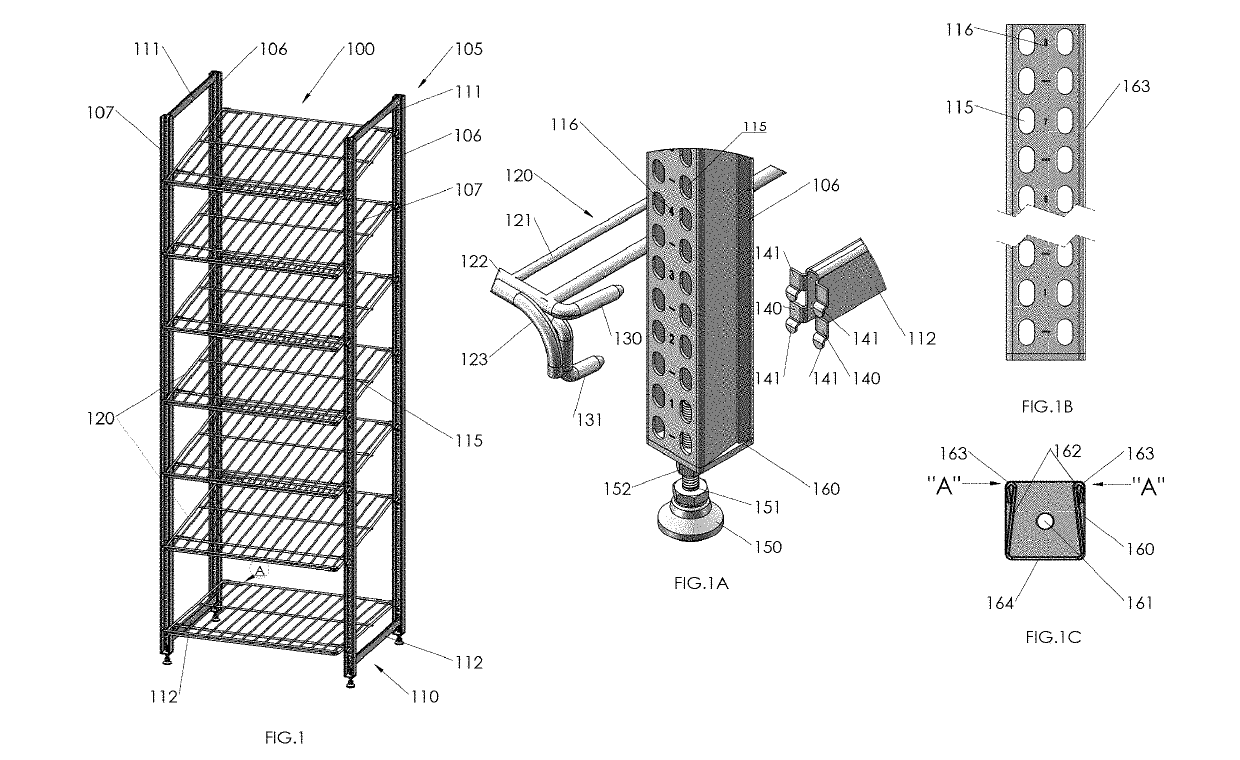
[0030]FIG. 4D shows a cross-member 450 suitable for use in conjunction with uprights 105 of the present disclosure. Cross-member 450 includes bar 410 having a vertical portion 411 and a horizontal portion 412, with vertical portion 411 and horizontal portion 412 substantially perpendicular to each other, and a plurality of support elements 430 similar to those shown in FIG. 4A. In the embodiment shown in FIG. 4D, cross-member 450 includes a pair of “U”-shaped end brackets 460. Each end bracket 460 each includes an end wall 461, a first angled surface 462, a second angled surface 463, and an end loop 464. End wall 461 is sized and configured to match flat section 164 of upright 105. Each first angled surface 462 is sized and configured to match leg 162. Each second angled surface 463 is angled away from first angled surface 462 so that end loop 464 can matingly engage hem 163. The structures and relationships are better seen in FIGS. 4E-4F. In the embodiment shown in FIGS. 4D-4F, end...


PUM


Abstract

Disclosed are rack shelving systems in-door coolers. The rack shelving systems are easily adjusted height-wise between adjacent shelves and can also be quickly adjusted between a flat shelf configuration and a gravity-feed configuration due to the configuration of different length prongs the attach the shelves to uprights that may have an angled surface with a hem be of a or typical U-shape. The rack shelving systems are also expandable width-wise to accommodate any number of cooler doors due to two rows of parallel slots on each upright that are configured to accept the prongs of shelves attached to adjacent uprights. The rack shelving systems very simple in design and are made up of as few as three (3) different parts: uprights, shelves, and cross-member. The rack shelving systems preferably further include feet/wheels for support and mobility.

Description

BACKGROUND1. Field of the Disclosure[0001]The present disclosure relates generally to rack shelving systems. More particularly, the present disclosure relates to rack shelving systems for in-door coolers.2. Description of Related Art[0002]Items, such soda, beer and water are frequently displayed in rows in refrigerated coolers having doors that may either slide or rotate to open to provide access to the interior of the cooler and to the refrigerated item. Generally, the state-of-the-art shelving systems that hold and display the refrigerated items are in a relatively “fixed” configuration, i.e., either flat or gravity-feed shelves, so that converting from one configuration to the other is difficult and time-consuming. Moreover, the state-of-the-art shelving systems that hold and display the refrigerated items are also in a relatively “fixed” configuration with respect to the height between adjacent shelves, making adjustment thereof also difficult and time-consuming. Finally, the st...

Claims


Application Information

Patent Timeline
IPC IPC(8): A47B57/04A47B96/02F25D25/02
CPCA47B57/04A47B96/021F25D25/02F25D2325/023A47B47/027
Inventor MILLER, JR., DONALD J.SUN, YEYANG
Owner SUNGAL
Why Eureka
Try Eureka