Three-dimensional shaping device
- Summary
- Abstract
- Description
- Claims
- Application Information
AI Technical Summary
Benefits of technology
Problems solved by technology
Method used
Image
Examples
first embodiment
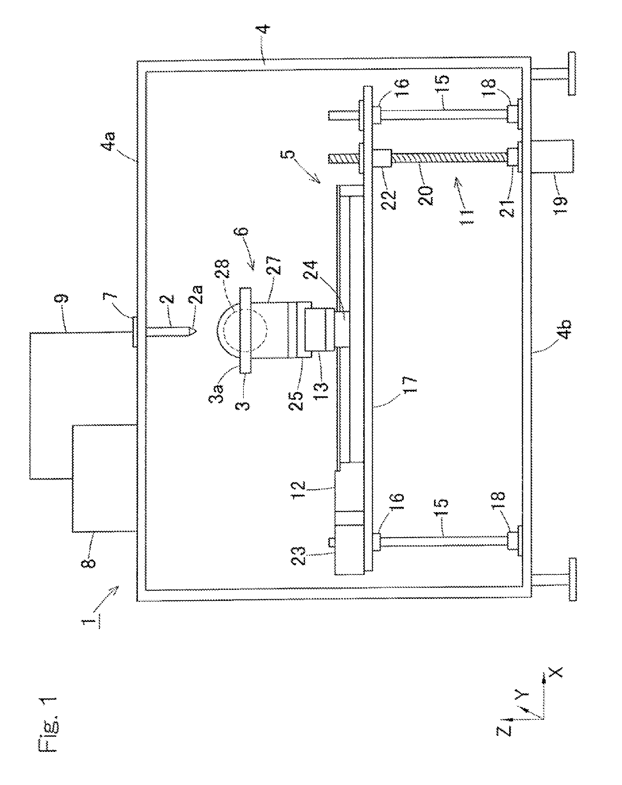
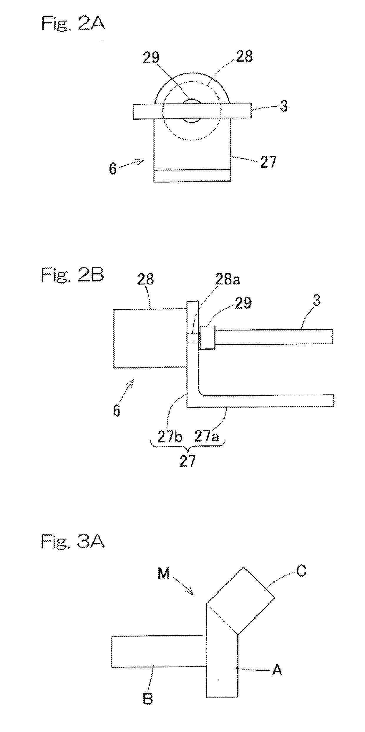
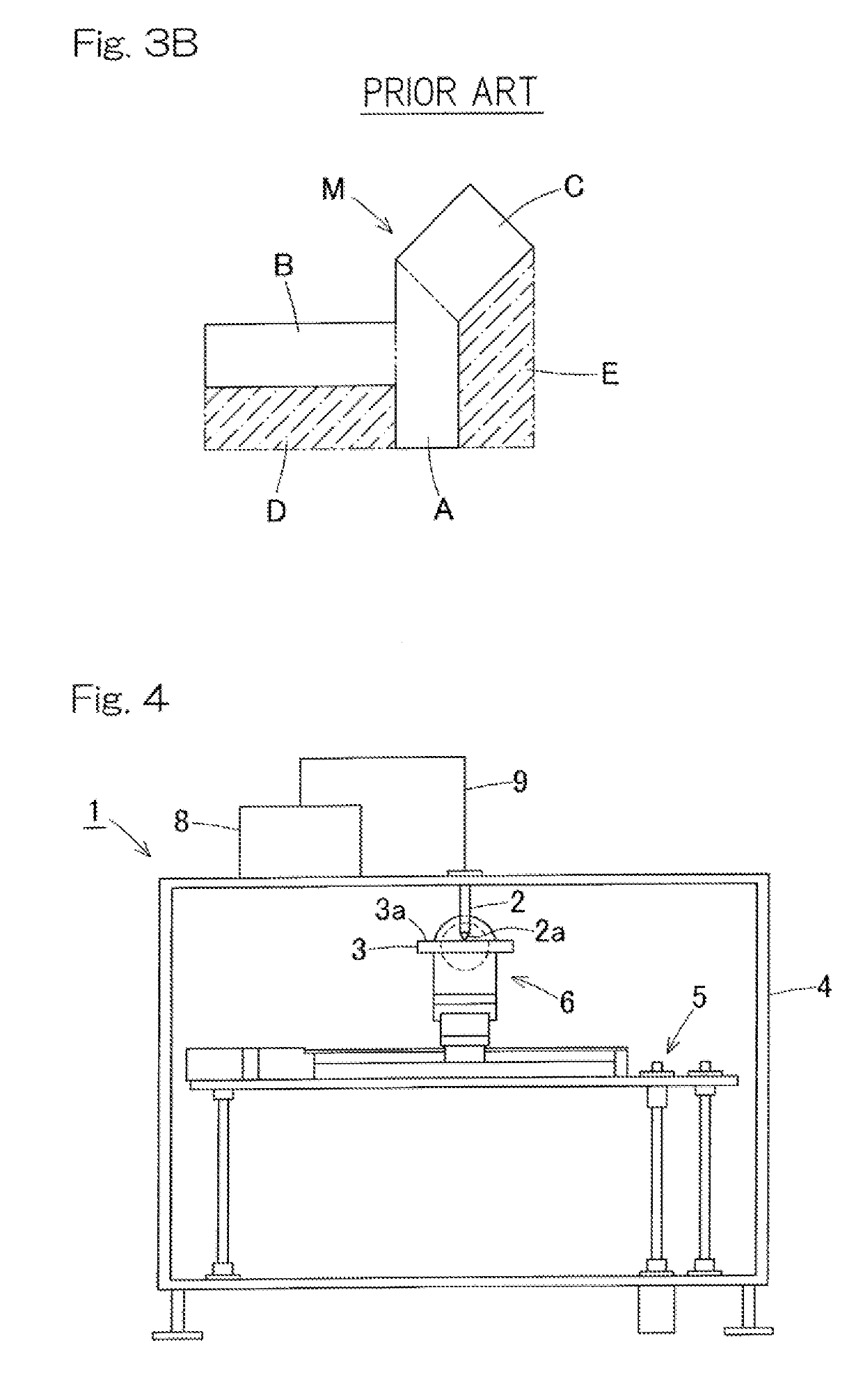
[0052]FIG. 1 is a front view showing a schematic configuration of a three-dimensional shaping device according to a first embodiment of the present invention. The three-dimensional shaping device 1 is a device for molding a shaped product through a fused deposition modeling method, in which raw material melted by heat so as to be fluidic is discharged through a nozzle 2a of a discharge head 2 and is cured on a shaping table 3. This operation is repeated while the relative position between the discharge head 2 and the shaping table 3 is being changed, thereby molding a shaped product in which the cured raw material is stacked in layers. As the raw material, for example, a resin having a property of being melted by heat is used.
[0053]The three-dimensional shaping device 1 includes a box-like mount 4 having a rectangular front shape with legs. On a lower portion of the mount 4, a linear motion mechanism 5 movable in three mutually orthogonal axial directions is disposed. The linear mot...
second embodiment
[0069]FIG. 10 is a front view showing a schematic configuration of a three-dimensional shaping device according to a second embodiment of the present invention. In the three-dimensional shaping device 1, the rotation unit 6 is implemented by a link actuation device L having two degrees of rotational freedom. The other components are the same as those in the first embodiment. The same components as those in the first embodiment described above are denoted by the same reference numerals, and the description thereof is omitted.
[0070]As shown in FIG. 11, the link actuation device L includes a parallel link mechanism 30 and a plurality of posture-controlling actuators 31 for actuating the parallel link mechanism 30. FIG. 12 and FIG. 13 are perspective views selectively showing only the parallel link mechanism 30, and the state of the parallel link mechanism 30 is different between FIG. 12 and FIG. 13. As shown in FIG. 11 to FIG. 13, in the parallel link mechanism 30, a distal-end-side li...
third embodiment
[0098]FIG. 16 is a front view showing a schematic configuration of a three-dimensional shaping device according to a third embodiment of the present invention. In the three-dimensional shaping device 1, the rotation unit 6 is implemented by the link actuation device L as is the case with the second embodiment described above. In the third embodiment, the configuration of the linear motion mechanism 5 is different from that in the second embodiment. The other components are the same as those in the second embodiment. The same components as those in the second embodiment are denoted by the same reference numerals, and the description thereof is omitted.
[0099]The linear motion mechanism 5 in the third embodiment includes the Z-axis linear motion portion 11, the X-axis linear motion portion 12, and the Y-axis linear motion portion 13 as is the case with the second embodiment. However, the arrangement of the linear motion portions 11 to 13 is different from that in the second embodiment....
PUM
| Property | Measurement | Unit |
|---|---|---|
| Angle | aaaaa | aaaaa |
Abstract
Description
Claims
Application Information
 - R&D
- Intellectual Property
- Life Sciences
- Materials
- Tech Scout
- Unparalleled Data Quality
- Higher Quality Content
- 60% Fewer Hallucinations
Browse by: Latest US Patents, China's latest patents, Technical Efficacy Thesaurus, Application Domain, Technology Topic, Popular Technical Reports.
© 2025 PatSnap. All rights reserved.Legal|Privacy policy|Modern Slavery Act Transparency Statement|Sitemap|About US| Contact US: help@patsnap.com


