

Method for applying oil agent to work
- Summary
- Abstract
- Description
- Claims
- Application Information
AI Technical Summary
Benefits of technology
Problems solved by technology
Method used
Image

Examples
first example
See FIGS. 1 and 2
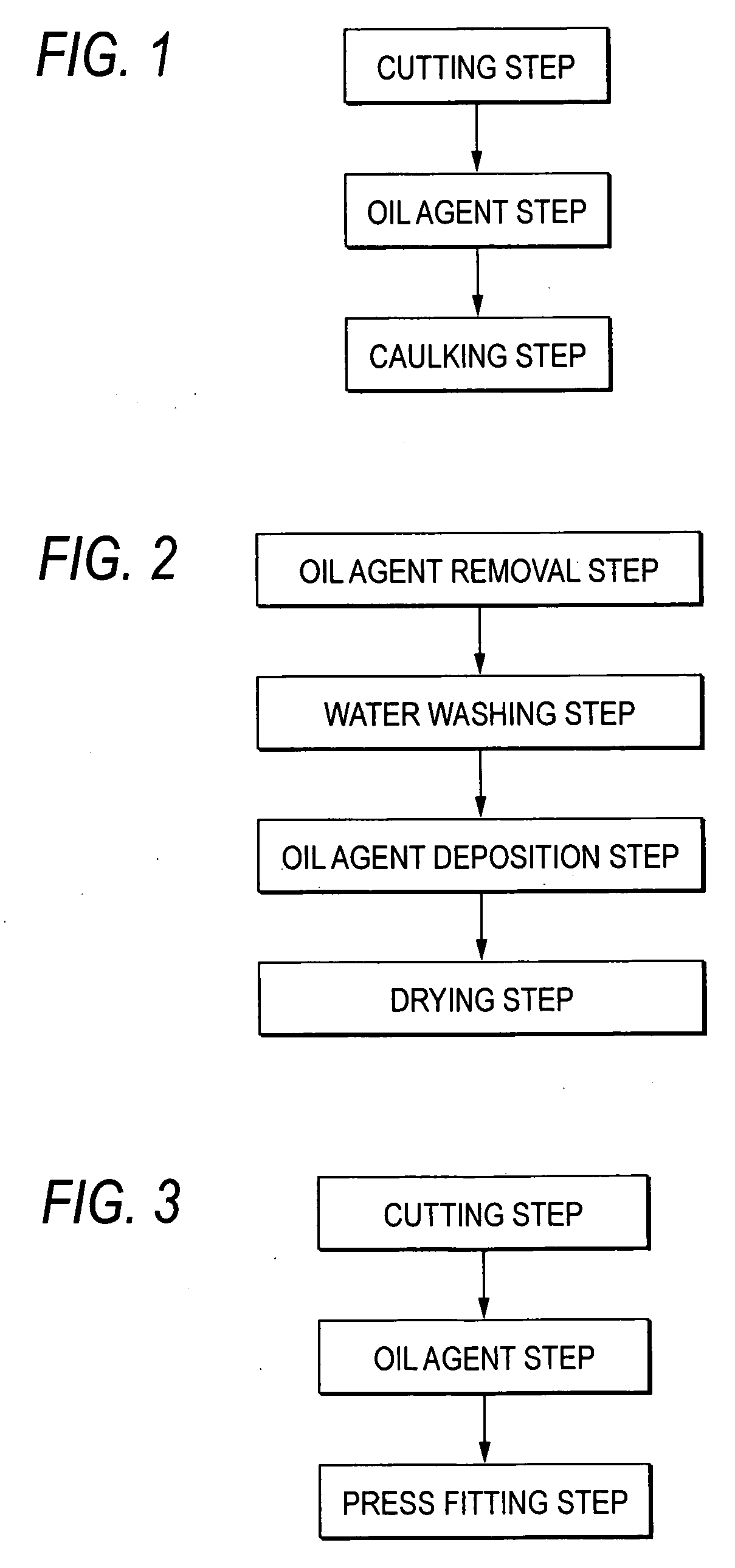
[0027] In this example, each workpiece is a metal component of a transport machine and made of stainless steel. As shown in FIG. 1, these components go through a “cutting step”, an “oil agent step” and a “caulking step” successively. In the “oil agent step”, a method of depositing an oil agent according to this example is carried out. The “caulking step” is a kind of plasticizing.
[0028] A cutting oil agent used for cooling, lubrication or chip removal is deposited and remains on the workpieces cut by the “cutting step”. The amount of the remaining oil agent deposited varies widely and is not suitable for the “caulking step” which is the post-step. In the “caulking step”, it is necessary to provide an adequate amount and kind of oil agent suitable for lubrication to reduce friction with a caulking tool and cooling of the friction portion.
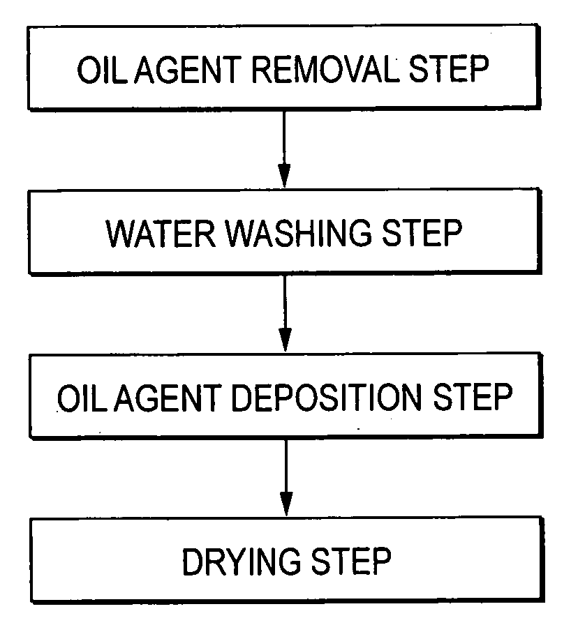
[0029] Therefore, as shown in FIG. 2, the workpieces cut by the “cutting step” which is the pre-step go through an “oil agent rem...
second example
See FIGS. 3 and 2
[0042] In this example, each workpiece is a metal component of a fluid machine and made of stainless steel. As shown in FIG. 3, the components go through a “cutting step”, an “oil agent step” and a “press fitting step” successively. In the “oil agent step”, the method of depositing an oil agent according to this example is carried out. The “press fitting step” is a kind of assembling.
[0043] The cutting oil agent used for cooling, lubrication and chip removal is deposited and remains on the workpieces cut by the “cutting step”. The amount of the remaining deposited oil agent varies widely and is not suitable for the “press fitting step” after that. In the “press fitting step”, a shaft portion of some workpiece is press-fitted into a hole portion of some workpiece. Accordingly, it is necessary to provide a lubricating oil agent for reducing friction at the time of press fitting.
[0044] Therefore, the workpieces cut by the “cutting step” which is the pre-step go throu...
third example
See FIGS. 3 and 2
[0051] In this example, each workpiece is a metal component of an internal combustion engine and made of an aluminum alloy. As shown in FIG. 3, the components go through the “cutting step”, the “oil agent step” and the “press fitting step” successively in the same manner-as in the second example. In the “oil agent step”, the method of depositing an oil agent according to this embodiment is carried out.
[0052] The workpieces cut by the “cutting step” which is the pre-step go through the “oil agent removal step”, the “water washing step”, the “oil agent deposition step” and the “drying step” successively as shown in FIG. 2 in the same manner as in the second example in place of the “oil agent step” before the “press fitting step” in order to deposit an oil agent suitable for the “press fitting step” which is the post-step.
[0053] A large number of workpieces are put in a wire mesh cage. The workpieces are immersed in a degreasing solution in the “oil agent removal ste...
PUM
| Property | Measurement | Unit |
|---|---|---|
| Concentration | aaaaa | aaaaa |
| Solubility (mass) | aaaaa | aaaaa |
Abstract
Description
Claims
Application Information