Turn-up Method and a Turn-up Device for a Reel-up for Reeling of Fiber Webs

Active Publication Date: 2019-08-08
VALMET TECH OY
View PDF3 Cites 0 Cited by
  • Summary
  • Abstract
  • Description
  • Claims
  • Application Information

AI Technical Summary

Benefits of technology

The invention provides a new method and device for turning up fiber webs during the process of reeling them onto a reel. This new method and device have several advantages over existing methods and devices. Firstly, it reduces the number of defective parts formed during the process. Secondly, it makes it easier to control the rejection of defective parts. Thirdly, it minimizes the distance traveled by each nozzle, making the movement of the nozzle easier to control. Overall, this new method and device can improve the quality of fiber webs during the reeling process.

Problems solved by technology

Also in this arrangement long travel distance for the nozzles are needed as both travel from one edge of the fiber web to the other edge and thus problems relating to control of the long movement of the nozzles may occur.
In the known methods and devices for turn-up several disadvantages and problems may occur: Often in connection with the methods and devices known from prior art a lot of space is needed for the equipment and thus it might be difficult to find a cost-effective solution for the turn-up device.

Method used


Image

  • Turn-up Method and a Turn-up Device for a Reel-up for Reeling of Fiber Webs
  • Turn-up Method and a Turn-up Device for a Reel-up for Reeling of Fiber Webs
  • Turn-up Method and a Turn-up Device for a Reel-up for Reeling of Fiber Webs

Examples


Embodiment Construction

[0033]During the course of the following description like numbers and signs will be used to identify like elements according to the different views which illustrate the invention and its advantageous examples. In the figures some repetitive reference signs have been omitted for clarity reasons.

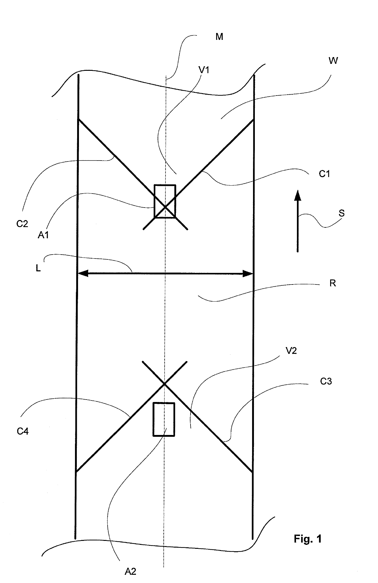
[0034]In FIG. 1 schematically shows a fiber web travelling in direction S, i.e., the machine direction. Cutting of the web is carried out by means of two water jet nozzles moving in a transverse or a cross-machine direction in relation to the travelling i.e., machine direction S, of the fiber web W. The water jet nozzles start their movement from the edges of the fiber web W and move toward the imaginary center line M of the fiber web W and cutting pressure from a source of cutting pressure is provided to the water jet nozzles i.e., to form a water jet, and two cuts C1, C2 to the fiber web are formed, which cuts C1, C2 sever the fiber web W in the cross-direction of the fiber web. i.e. in a tr...


PUM

PropertyMeasurementUnit
Timeaaaaaaaaaa
Timeaaaaaaaaaa
Widthaaaaaaaaaa

Abstract

In a turn-up method for a reel-up for reeling of fiber webs, a web travelling in direction (S) is cut by two water jet nozzles moving in a transverse direction in relation to the web travelling direction (S). Two cuts (C1, C2) are formed by two water jet nozzles starting from the edges of the web (W) and moving to the web center where the cuts (C1, C2) cross or meet forming a V-shaped tail end (V1). After the cuts the movement of the water jet nozzles is stopped and after the return movement of the water jet nozzles, cutting is started again from the center toward the edges so that the web W is cut by two cuts (C3, C4) and a substantially V-shaped beginning end (V2) to the web W is formed and between the cuts (C1, C2) for the tail end (V1) and the cuts (C3, C4) for the beginning end (V2) there is formed one web reject part (R) with two substantially V-shaped cuts. A turn-up device for a reel-up for reeling of fiber webs has two water jet nozzles, in which the cutting by the water jet nozzles (10,12) may be stopped between cutting of a tail end (V1) and cutting of a beginning end (V2) for a selected time for forming only, wherein there is one reject part (R) in the turn-up and the cross-direction travel distance (L1, L2) of each nozzle is substantially shorter than the width (L) of the web (W).

Description

CROSS REFERENCES TO RELATED APPLICATIONS[0001]This application claims priority on application EP 18155283, filed Feb. 6, 2018, the disclosure of which is incorporated by reference herein.STATEMENT AS TO RIGHTS TO INVENTIONS MADE UNDER FEDERALLY SPONSORED RESEARCH AND DEVELOPMENT[0002]Not applicable.BACKGROUND OF THE INVENTION[0003]The present invention relates to reel-ups for reeling of fiber webs. In particular, the present invention relates to a turn-up method for a reel-up for reeling of fiber webs which utilizes two water jets cutting inwardly from the web edges.[0004]As known, fiber webs, such as paper or board webs, are manufactured in machines together forming a fiber web manufacturing line, which may be hundreds of meters long. Modern paper machines may produce more than 450,000 tons of paper per year. The speed of a paper machine may exceed 2,000 m / min and the width of a paper web may be more than 11 meters.[0005]As known from the prior art, fiber web producing processes ty...

Claims


Application Information

Patent Timeline
IPC IPC(8): B65H19/26B65H18/08B65H19/28B65H19/29
CPCB65H19/26B65H18/08B65H19/286B65H19/29B65H2406/211B65H2801/84B65H19/265B65H19/28B65H2301/41898B65H2301/5151B65H2301/51534B65H2511/25B65H2513/51B65H2601/511
Inventor HAAPANEN, JAAKKOPENTTILA, KIMMORIIHELA, VESAFORSSEN, KAI
Owner VALMET TECH OY
Why Eureka
Try Eureka