Stress Test Jig and Stress Test Method

a test specimen and stress test technology, applied in the field of stress test jig and stress test method, can solve the problems of corrosive environment of oil wells, etc., and achieve the effect of suppressing buckling in the test specimen

Active Publication Date: 2019-08-08
NIPPON STEEL CORP
View PDF0 Cites 5 Cited by
  • Summary
  • Abstract
  • Description
  • Claims
  • Application Information

AI Technical Summary

Benefits of technology

[0032]According to the present invention, buckling in a test specimen can be suppressed without covering an area around the parallel portion. Accordingly, the relationship between stress and strain in metal products can be properly evaluated.

Problems solved by technology

The oil wells have a corrosive environment.
However, in a compression test of steel products, buckling in a test specimen causes a problem.
Such tilting may cause buckling in the test specimen.

Method used


Image

  • Stress Test Jig and Stress Test Method
  • Stress Test Jig and Stress Test Method
  • Stress Test Jig and Stress Test Method

Examples


example

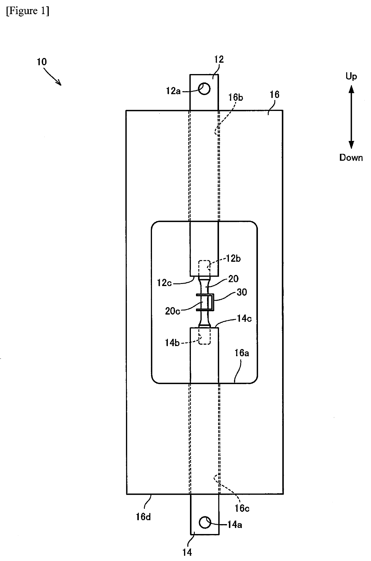
[0062]To check advantageous effects of the present invention, using a jig 10 and a stress testing machine 40 having the above-mentioned configuration, a compressive load and a tensile load were repeatedly applied to a test specimen 20 so as to investigate the relationship between stress and strain which are generated in the test specimen 20.

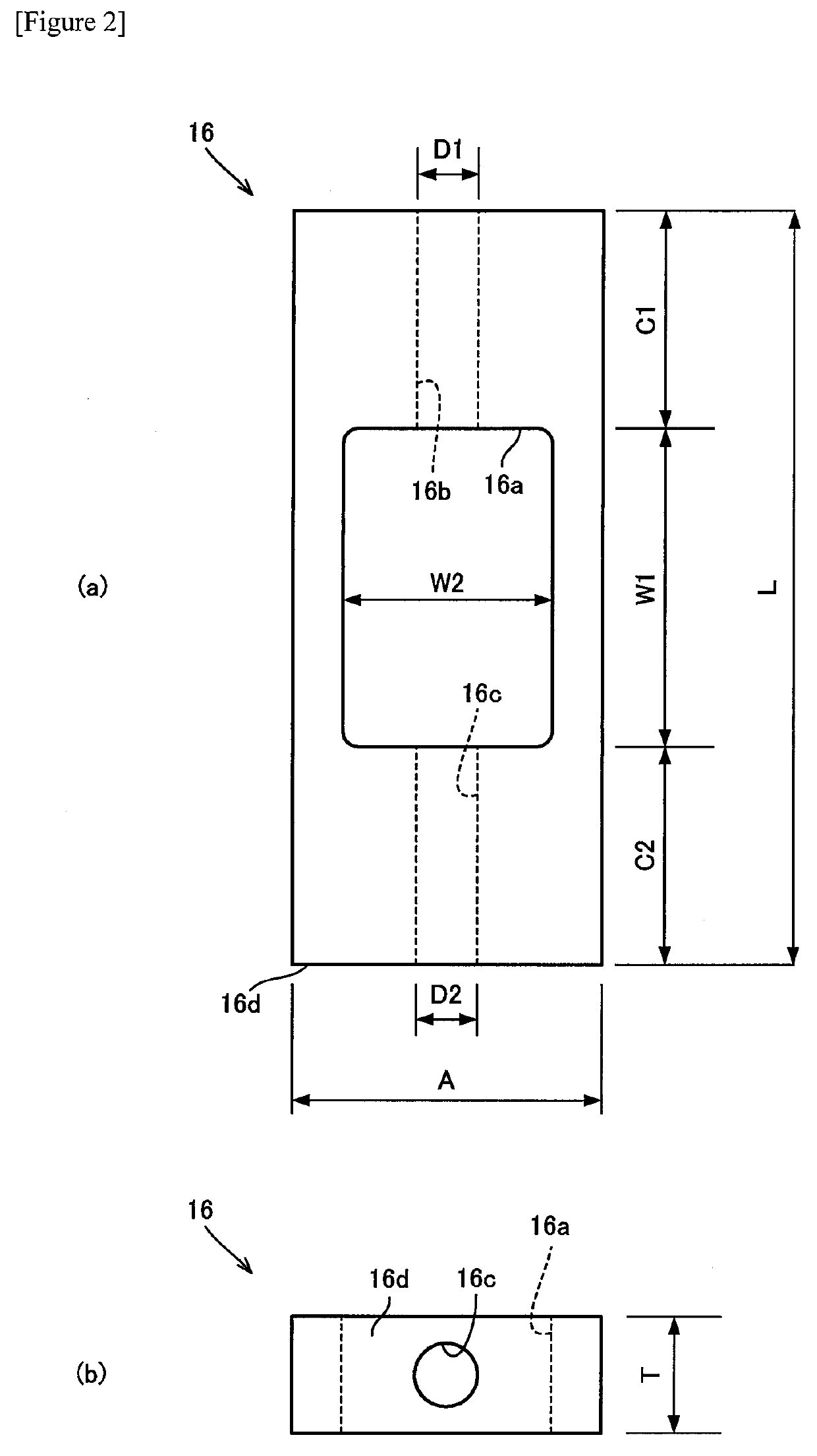
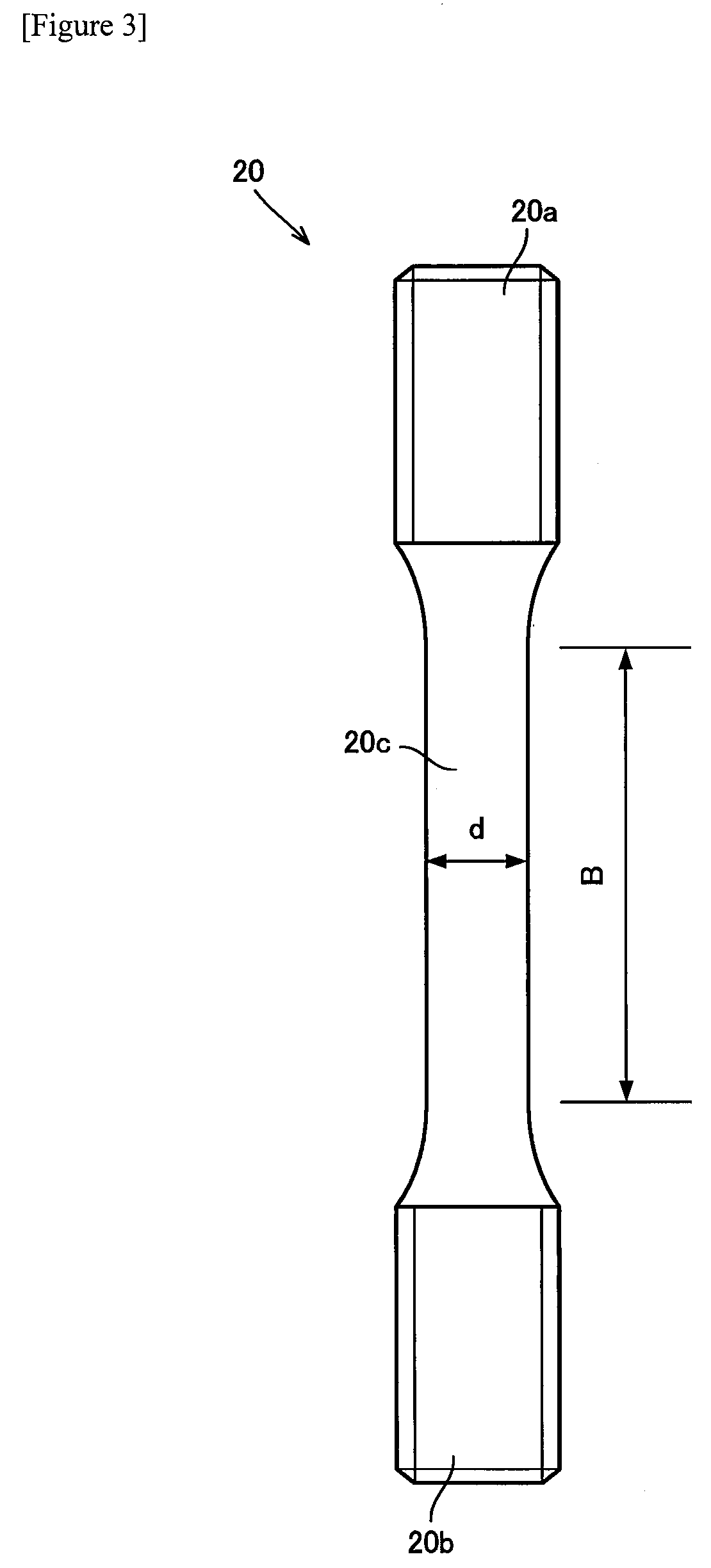
[0063]In this example, a frame 16 provided with C-shaped steel sections 18a, 18b (see FIG. 5) was used. Referring to FIG. 2, each of a length C1 and a length C2 was set to 200 mm, a length W1 was set to 150 mm, a width W2 was set to 100 mm, a width A was set to 130 mm, a thickness T was set to 50 mm, each of a diameter D1 and a diameter D2 was set to 32 mm, and a width E (see FIG. 5) was set to 200 mm. Further, referring to FIG. 3, in the axial direction of the test specimen 20, each of a length of an upper end portion 20a and a length of a lower end portion 20b was set to 6.3 mm, a length B of a parallel portion 20c was set to 8.0 mm, a diameter...


PUM

PropertyMeasurementUnit
length W1aaaaaaaaaa
length W1aaaaaaaaaa
lengthaaaaaaaaaa

Abstract

A stress test the jig 10 includes an upper cylinder 12, a lower cylinder 14, and a frame 16. The frame 16 has an accommodating space 16a, an upper through hole 16b, and a lower through hole 16c. A test specimen 20 is disposed in the accommodating space 16a, the upper cylinder 12 is inserted into the upper through hole 16b, and the lower cylinder 14 is inserted into the lower through hole 16c. The upper cylinder 12 and the lower cylinder 14 fix the test specimen 20 such that the test specimen 20, the upper cylinder 12, and the lower cylinder 14 are positioned coaxially.

Description

TECHNICAL FIELD[0001]The present invention relates to a stress test jig and a stress test method, and particularly relates to a jig and a test method which can be preferably used in a stress test for a rod-shaped test specimen.BACKGROUND ART[0002]Oil country tubular goods (OCTG) are used in oil wells and gas wells (in this specification, oil wells and gas wells are collectively referred to as “oil wells”). The oil wells have a corrosive environment. Accordingly, oil country tubular goods are required to have corrosion resistance. Types of oil country tubular goods include a casing and a tubing. The casing is inserted into a well bore. A gap formed between the casing and the wall of the well bore is filled with cement so that the casing is fixed in the well bore. The tubing is inserted into the casing, and a production fluid, such as oil and gas, passes through the tubing. The oil country tubular goods are also required to have high strength together with corrosion resistance. In gen...

Claims


Application Information

Patent Timeline
Patent Type & Authority Applications(United States)
IPC IPC(8): G01N3/04G01N3/08
CPCG01N3/04G01N3/08G01N2203/0017G01N2203/0019G01N2203/0423
Inventor KURODA, KOICHIYANAGA, DAISAKUSUZUKI, YUHEI
Owner NIPPON STEEL CORP
Why Eureka
Try Eureka