
Occupancy detection in a radio frequency wireless communication network

occupancy detection technology, applied in the field of occupancy detection in a radio frequency wireless communication network, can solve the problems of ineffective indoors, large amount of memory for storing data, and large number of dedicated sensors in the video sensor monitoring system

Active Publication Date: 2019-08-15
ABL IP HLDG
View PDF1 Cites 7 Cited by
  • Summary
  • Abstract
  • Description
  • Claims
  • Application Information

AI Technical Summary

Benefits of technology

This patent describes a system and method for automatically detecting occupancy in a wireless network using RF receivers. By transmitting RF signals and collecting data on them, the system can detect changes caused by the movement of an occupant and detect if someone is present. This technology can be used in various areas, such as in retail stores or sports arenas, to improve monitoring and provide better customer service.

Problems solved by technology

However, many of these systems have several disadvantages.
For example, the video sensor monitoring system requires a considerable number of dedicated sensors that are expensive and the system requires a large amount of memory for storing data.
However, such systems are generally less effective indoors or in other environments where satellite signals may be blocked, reducing accuracy of detecting the occupant in the area.
However, all the above methods require human effort and / or dedicated hardware (e.g. cameras, directional transmitters, etc.) that entail complexity and expense.
Also, an inaccurate detection of the occupant in a region can occur by detecting an object, which does not move when multiple transmitters are transmitting the RF signals from multiple different regions of the area.
Thus, the RF signal detected at one frequency is different from the RF signal detected at another different frequency, which results in change in the RSSI data.

Method used


Image

  • Occupancy detection in a radio frequency wireless communication  network
  • Occupancy detection in a radio frequency wireless communication  network
  • Occupancy detection in a radio frequency wireless communication  network

Examples


Embodiment Construction

[0025]In the following detailed description, numerous specific details are set forth by way of examples in order to provide a thorough understanding of the relevant teachings. However, it should be apparent that the present teachings may be practiced without such details. In other instances, well known methods, procedures, components, and / or circuitry have been described at a relatively high-level, without detail, in order to avoid unnecessarily obscuring aspects of the present teachings.

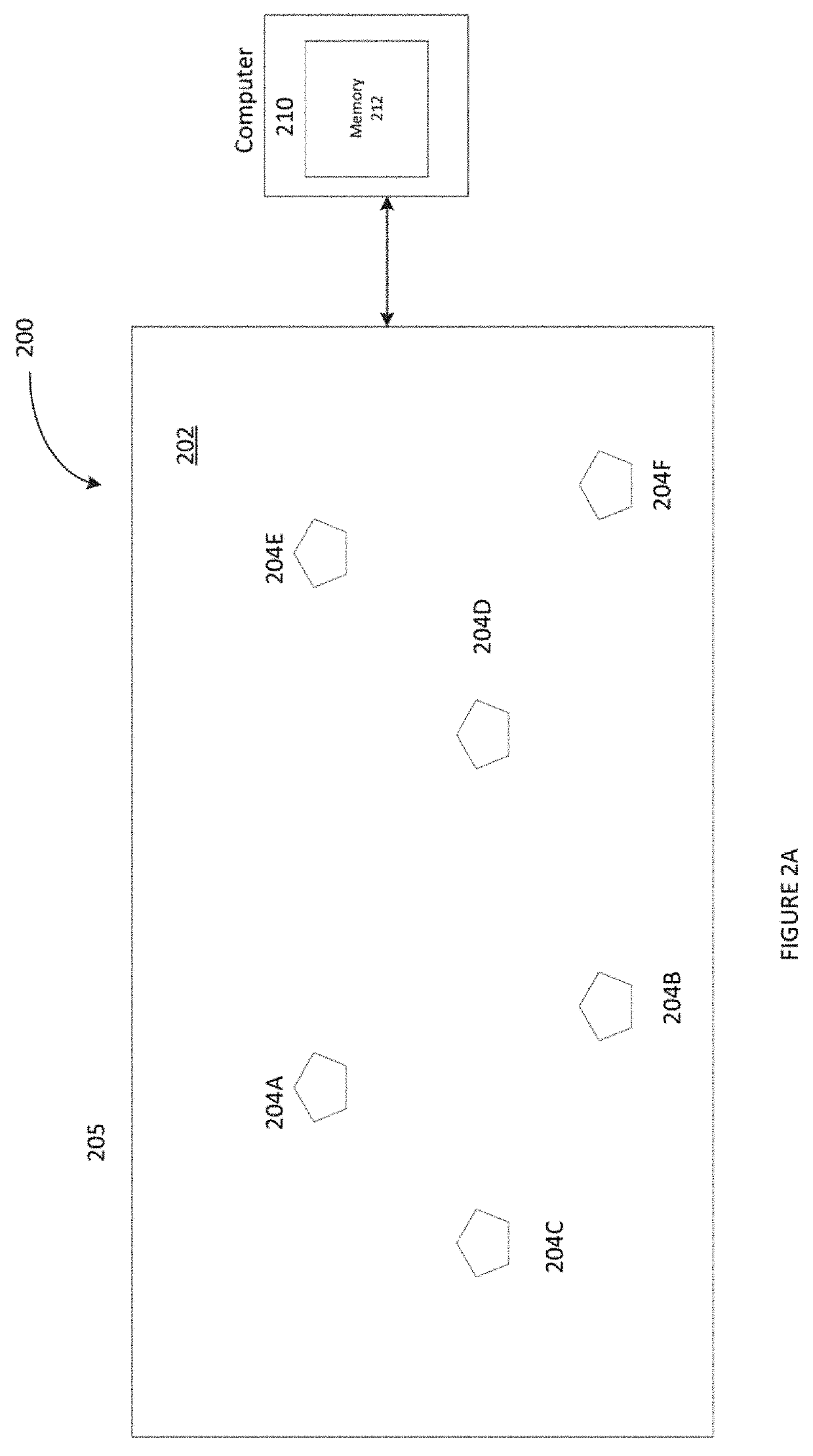
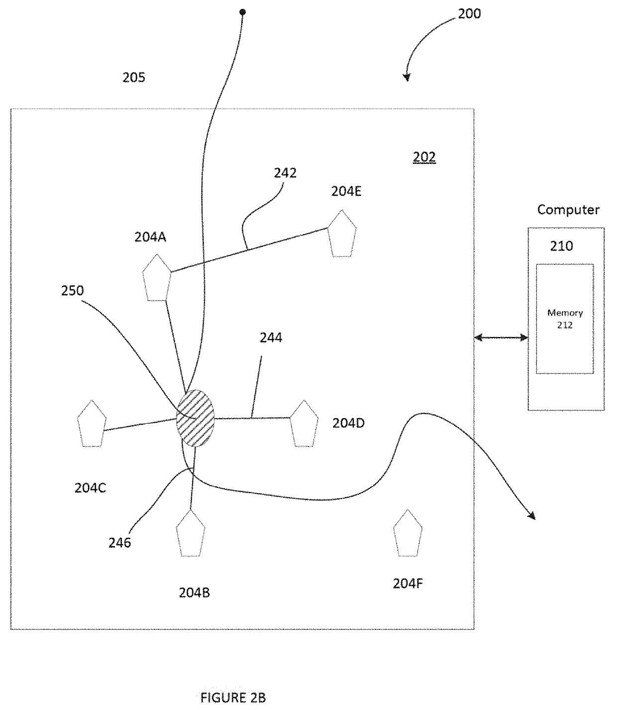
[0026]To provide improved occupancy detection in an area of a network, e.g. a radio frequency (RF) ad hoc wireless mesh network of a lighting system or the like, the present disclosure includes a system and method for exploiting properties of a configuration of the RF wireless network to detect an occupant in the area. Thus an occupancy is detected based on measurements of RF perturbations in an area or space and the properties.

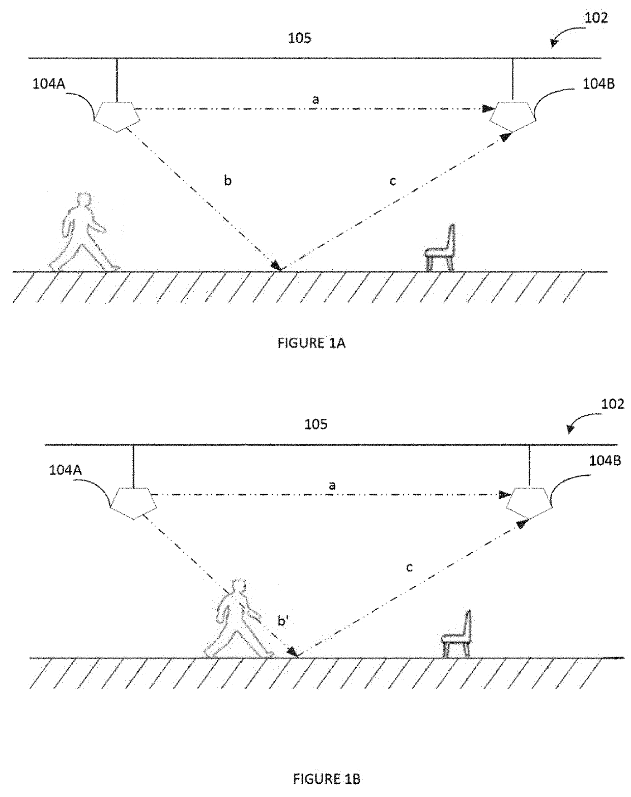
[0027]Referring to FIG. 1A, there is illustrated an example of a multipa...


PUM


Abstract

The disclosure provides an example of a system including a radio frequency (RF) wireless communication network (network) including a plurality of nodes in an area and a computer coupled to the network. Each of the nodes includes a transmitter and a receiver. At plurality of times, each transmitter transmits RF spectrum signals (signals) and each receiver receives the signals and also generates an indicator data of a signal characteristic of the received signal propagated in the network. When each time among the plurality of times is a current time, the computer obtains the indicator data of the signal, determines a modification in the indicator data at the current time from the indicator data at a preceding time due to a movement of an occupant in the area and detect an occupancy condition in the area based on the modification in the indicator data and a parameter of a configuration of the network.

Description

TECHNICAL FIELD[0001]The present subject matter relates to methods, systems and apparatuses for an occupancy detection in a radio frequency (RF) wireless communication network utilizing properties of the RF transceiver in the RF wireless communication network.BACKGROUND[0002]Information about the occupancy of a given finite area can have many uses, from safety enhancement to marketing science. Here, an “occupant” is typically a person but can also be an animal, a mobile machine, or any changeable aspect of the finite area that affects radio propagation and that it may be desirable to sense. Sensed occupancy information can vary in completeness and value: e.g., one may estimate the total number of occupants at a given time, estimate statistical aspects of occupants' movements over time, or estimate tracking the movements of occupants over time.[0003]Occupancy has been measured by manual count (e.g., at venue entrance), computer vision systems, electric-eye counters, and other methods...

Claims


Application Information

Patent Timeline
Patent Type & Authority Applications(United States)
IPC IPC(8): G01S13/56G01S13/00
CPCG01S13/56G01S13/003G01S3/78H05B47/115Y02B20/40
Inventor LU, YENPAOLU, MIN-HAO MICHAELMIU, MICHAEL
Owner ABL IP HLDG
Learn More