Card insertion structure
a card and insertion structure technology, applied in the field of card insertion structure, can solve the problem of not providing sufficient lock structur
- Summary
- Abstract
- Description
- Claims
- Application Information
AI Technical Summary
Benefits of technology
Problems solved by technology
Method used
Image
Examples
Embodiment Construction
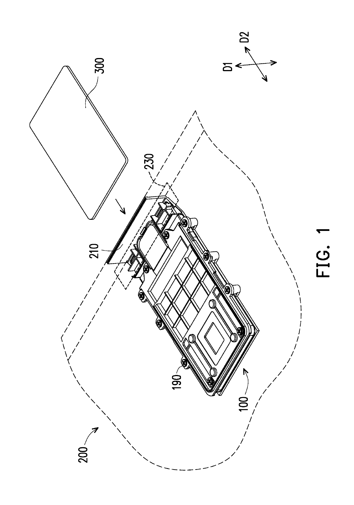
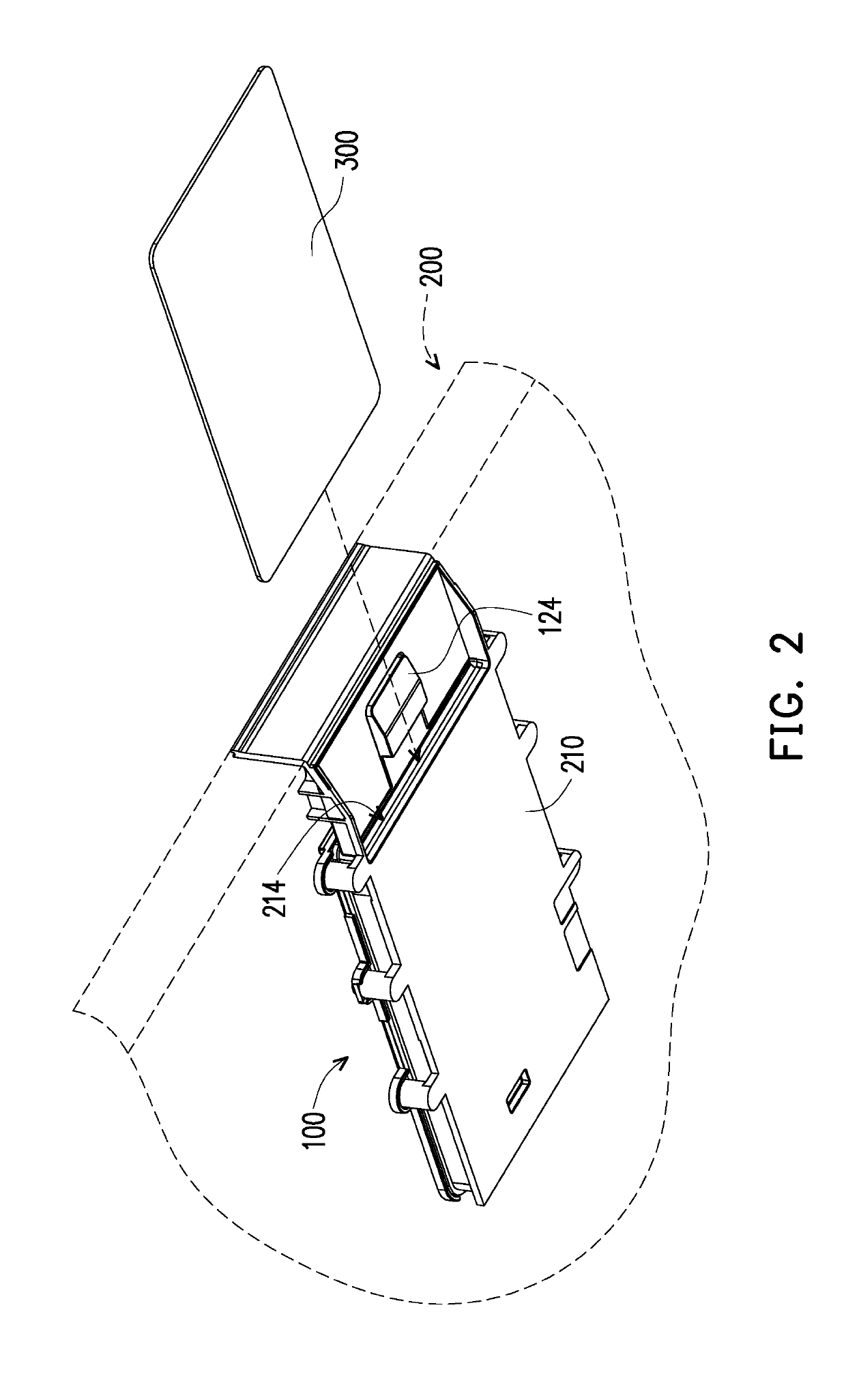
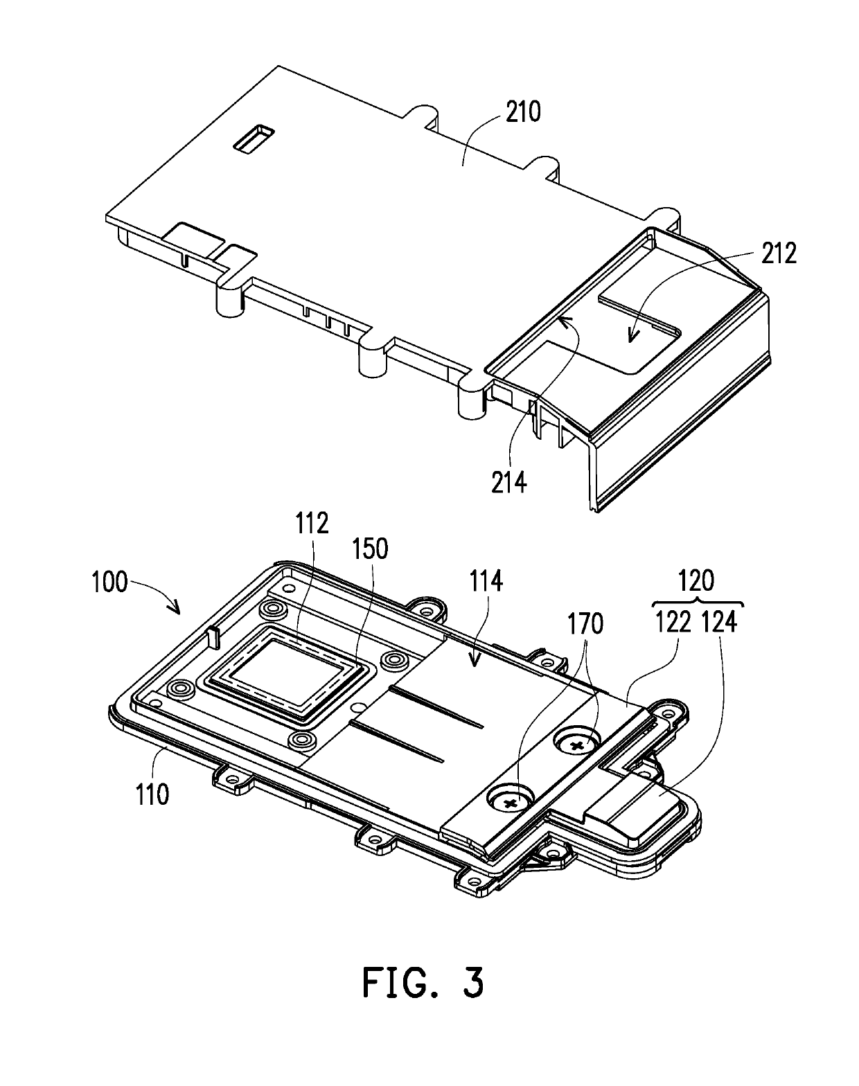
[0024]FIG. 1 is a partial schematic view of a card insertion structure applied to a portable electronic device according to an embodiment of the disclosure. FIG. 2 is a schematic view of FIG. 1 from another perspective. FIG. 3 is a schematic view illustrating initial assembly of the card insertion structure and corresponding housing. Referring to FIG. 1 to FIG. 3, in this embodiment, a card insertion structure 100 is disposed in a housing 210 of a portable electronic device 200 and is used to accommodate and position an electronic card 300 (e.g., an IC card, a smart card, etc.). Meanwhile, after the electronic card 300 is inserted into the housing 210 and carried on a stage 114, the control system (not shown) of the portable electronic device 200 can read the information in the inserted electronic card 300 through a reading module 112.
[0025]FIG. 4 and FIG. 5 are schematic views illustrating the respective assembly of the card insertion structure and the corresponding housing, which ...
PUM
 Abstract
Description
Claims
Application Information
 - R&D
- Intellectual Property
- Life Sciences
- Materials
- Tech Scout
- Unparalleled Data Quality
- Higher Quality Content
- 60% Fewer Hallucinations
Browse by: Latest US Patents, China's latest patents, Technical Efficacy Thesaurus, Application Domain, Technology Topic, Popular Technical Reports.
© 2025 PatSnap. All rights reserved.Legal|Privacy policy|Modern Slavery Act Transparency Statement|Sitemap|About US| Contact US: help@patsnap.com


