Wireless power transfer system

a power transfer system and wireless technology, applied in the direction of electrical equipment, circuit arrangements, etc., can solve the problem that the overall power conversion efficiency cannot maintain a stable value, and achieve the effect of maximizing the power conversion efficiency of the system

Active Publication Date: 2019-08-15
HONG KONG APPLIED SCI & TECH RES INST
View PDF4 Cites 4 Cited by
  • Summary
  • Abstract
  • Description
  • Claims
  • Application Information

AI Technical Summary

Benefits of technology

[0004]One example embodiment is a wireless power transfer system with a class DE inverter for power transfer to a load having an impedance that is variable. The wireless power transfer system includes a half-bridge circuit, a zero voltage switching (ZVS) tank, a shunt capacitor array, an evaluation circuit, and a controller. The half-bridge circuit has two transistors connected in series with each of the two transistors driven by a gate driving signal with a duty cycle. The ZVS tank and the shunt capacitor array are electrically connected with the half-bridge circuit. The ZVS tank includes two capacitors and an inductor. The shunt capacitor array has a capacitance that is tunable. The evaluation circuit calculates a power conversion efficiency of the system. The controller receives the power conversion efficiency from the evaluation circuit and generates control signals to adjust the duty cycle of the gate driving signal and to adjust the capacitance of the shunt capacitor array in order to maximize the power conversion efficiency of the system.

Problems solved by technology

Class DE inverters can further improve the power conversion efficiency of the wireless power transfer system at a certain load impedance, but the overall power conversion efficiency cannot maintain a stable value.
A major challenge of class DE inverters is how to keep the power conversion efficiency at a high level when the load impedance varies.

Method used


Image

  • Wireless power transfer system
  • Wireless power transfer system
  • Wireless power transfer system

Examples


Embodiment Construction

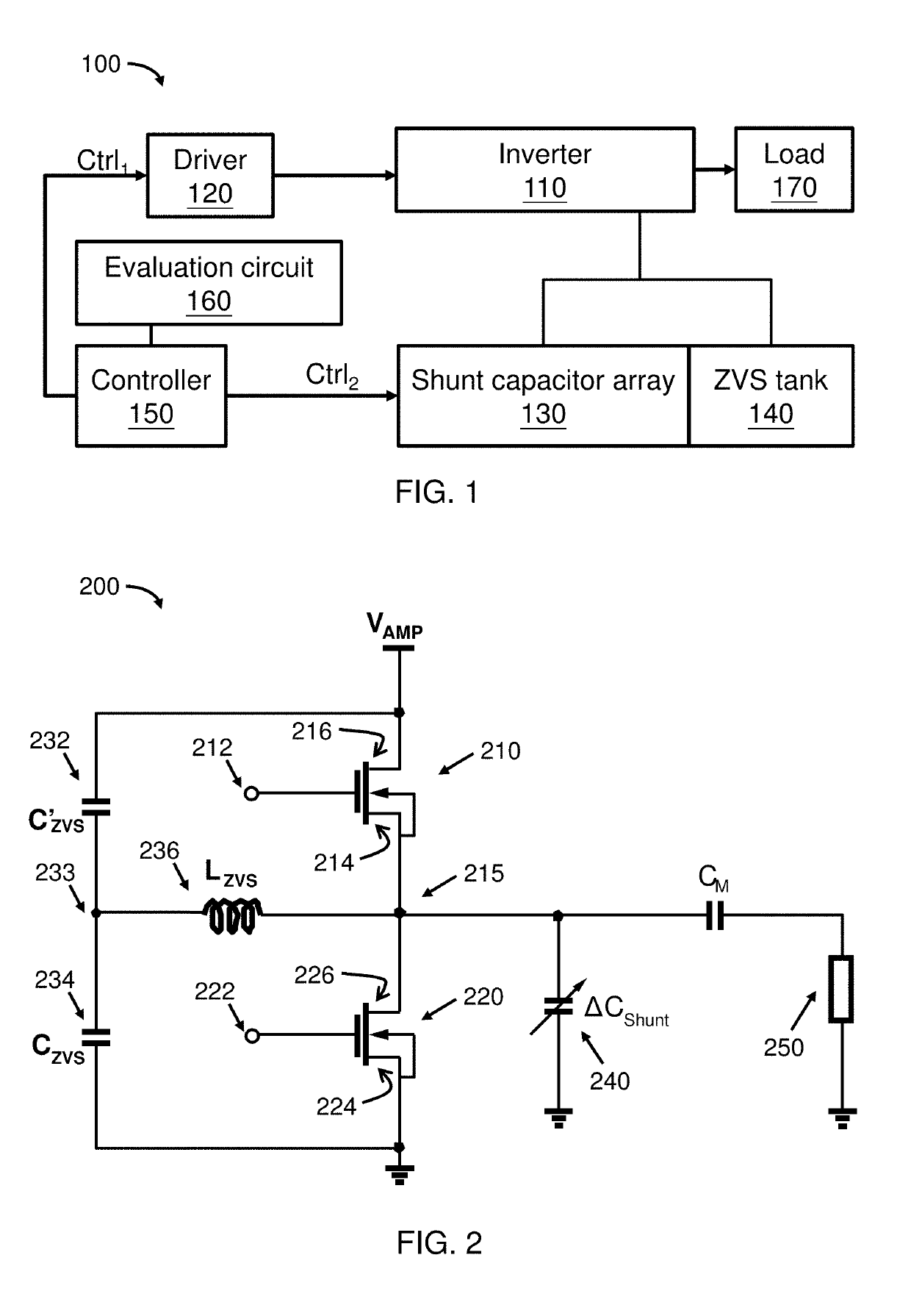
[0018]Example embodiments relate to wireless power transfer systems or wireless power transmitters and methods that supply power to a load wirelessly with maximized power conversion efficiency.

[0019]Wireless power transfer system transfers electrical power from a power source to an electrical load wirelessly. This system transfers electrical power ranging from microwatts to megawatts. The wireless power transfer system includes an inverter or an amplifier that converts a direct current (DC) signal to an alternating current (AC) signal, a transmitting (Tx) resonator, a receiving (Rx) resonator, and a rectifier. The rectifier converts the AC signal to DC signal and supplies power to the load directly. The wireless power transfer system is desired to keep a high power conversion efficiency when the load impedance fluctuates.

[0020]Example embodiments continuously, continually, or periodically adjust the driver of the amplifier and the shunt capacitance of the amplifier in order to impro...


PUM


Abstract

A wireless power transfer system with a class DE inverter for power transfer to a load. The wireless power transfer system includes a half-bridge circuit, a zero voltage switching (ZVS) tank, a shunt capacitor array, an evaluation circuit, and a controller. The half-bridge circuit has two transistors connected in series with each of the two transistors driven by a gate driving signal with a duty cycle. The ZVS tank and the shunt capacitor array are electrically connected with the half-bridge circuit. The ZVS tank includes two capacitors and an inductor. The shunt capacitor array has a capacitance that is tunable. The evaluation circuit calculates a power conversion efficiency of the system. The controller receives the power conversion efficiency from the evaluation circuit and generates control signals to adjust the duty cycle of the gate driving signal and to adjust the capacitance of the shunt capacitor array in order to maximize the power conversion efficiency of the system.

Description

FIELD OF THE INVENTION[0001]The present invention relates to a wireless power transfer system that supplies power to a load.BACKGROUND[0002]Wireless power transfer systems provide a convenient, safe, and reliable way to charge and power electrical devices. Traditionally, the inverters or amplifiers of the wireless power transfer system are ZVS class D inverters. The ZVS class D inverters achieve a relatively stable overall power conversion efficiency of the system. Class DE inverters can further improve the power conversion efficiency of the wireless power transfer system at a certain load impedance, but the overall power conversion efficiency cannot maintain a stable value. A major challenge of class DE inverters is how to keep the power conversion efficiency at a high level when the load impedance varies.[0003]New methods and systems that provide improved power conversion efficiency from the wireless power transfer system to the load will assist in advancing technological needs an...

Claims


Application Information

Patent Timeline
Patent Type & Authority Applications(United States)
IPC IPC(8): H02J50/12H02J50/05
CPCH02J50/12H02J50/05
Inventor CHEN, ZIANGCHEN, JUNLEE, HANG SANG
Owner HONG KONG APPLIED SCI & TECH RES INST
Why Eureka
Try Eureka