Power conversion device and method of driving the same

a technology of power conversion device and power conversion method, which is applied in the direction of electrical equipment without intermediate ac conversion, ac network circuit arrangement, electrical equipment, etc., can solve the problem of not being able to actively cope with the corresponding situation by changing the predetermined carrier frequency, and achieve the effect of maximizing power conversion efficiency

Inactive Publication Date: 2016-08-11
SAMSUNG SDI CO LTD
View PDF9 Cites 1 Cited by
  • Summary
  • Abstract
  • Description
  • Claims
  • Application Information

AI Technical Summary

Benefits of technology

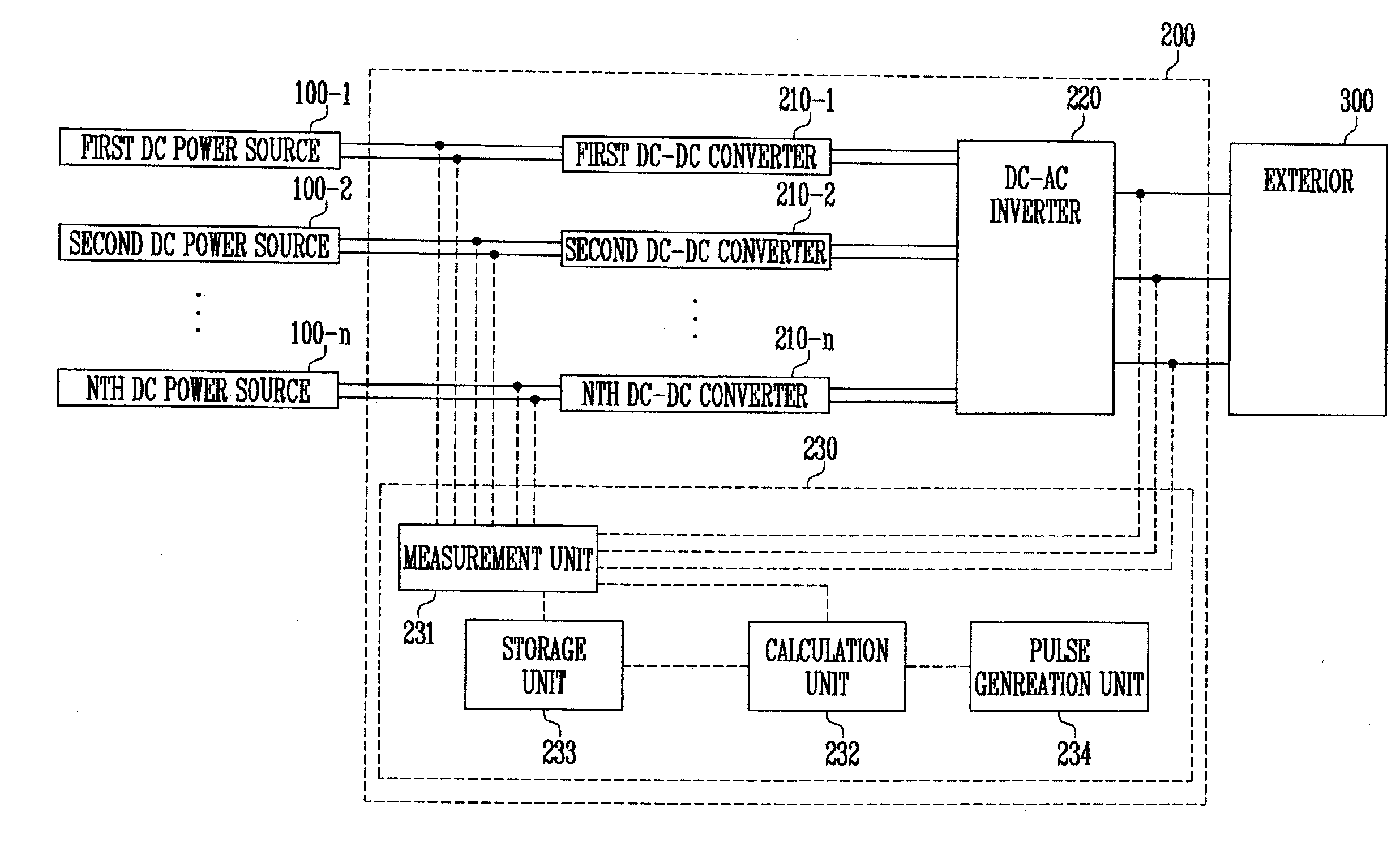
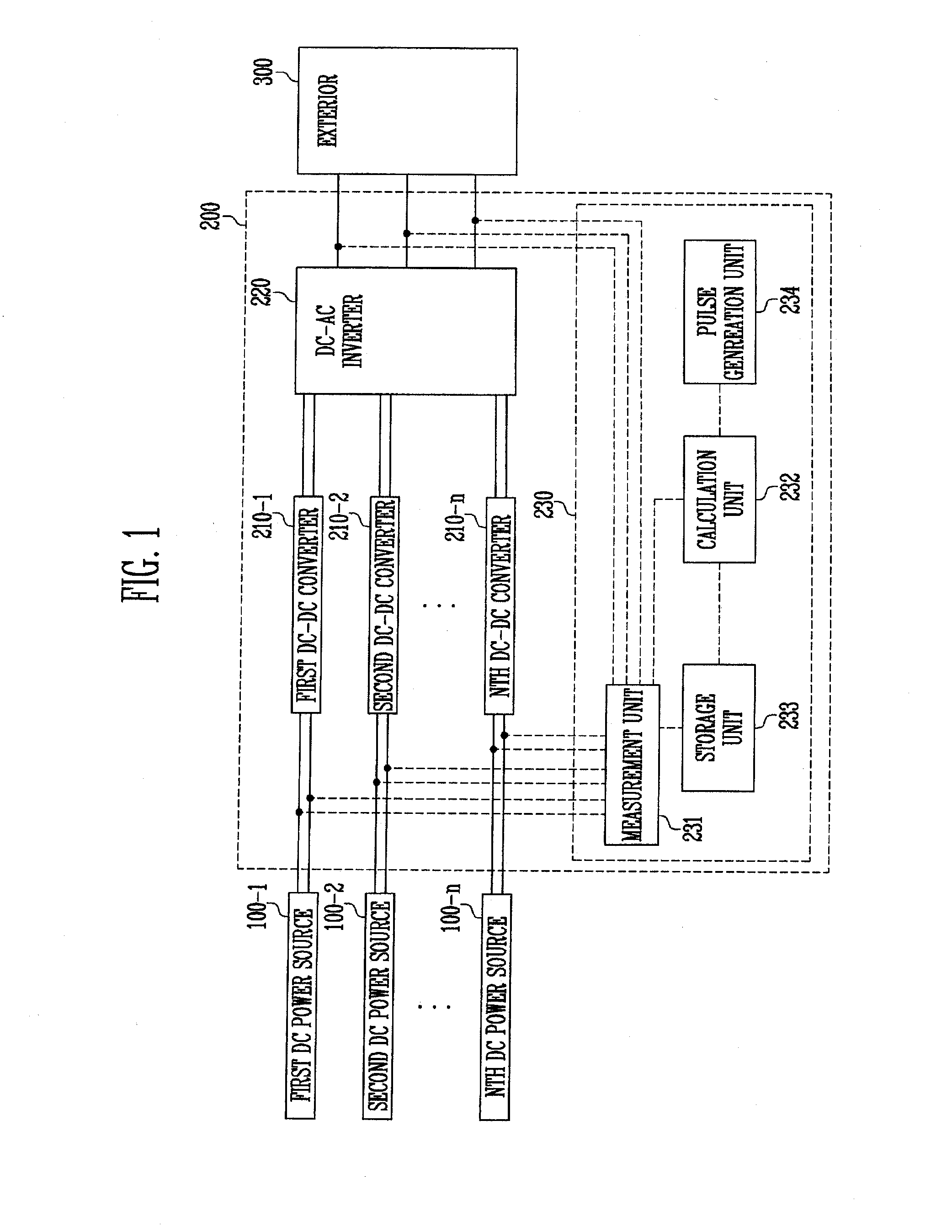
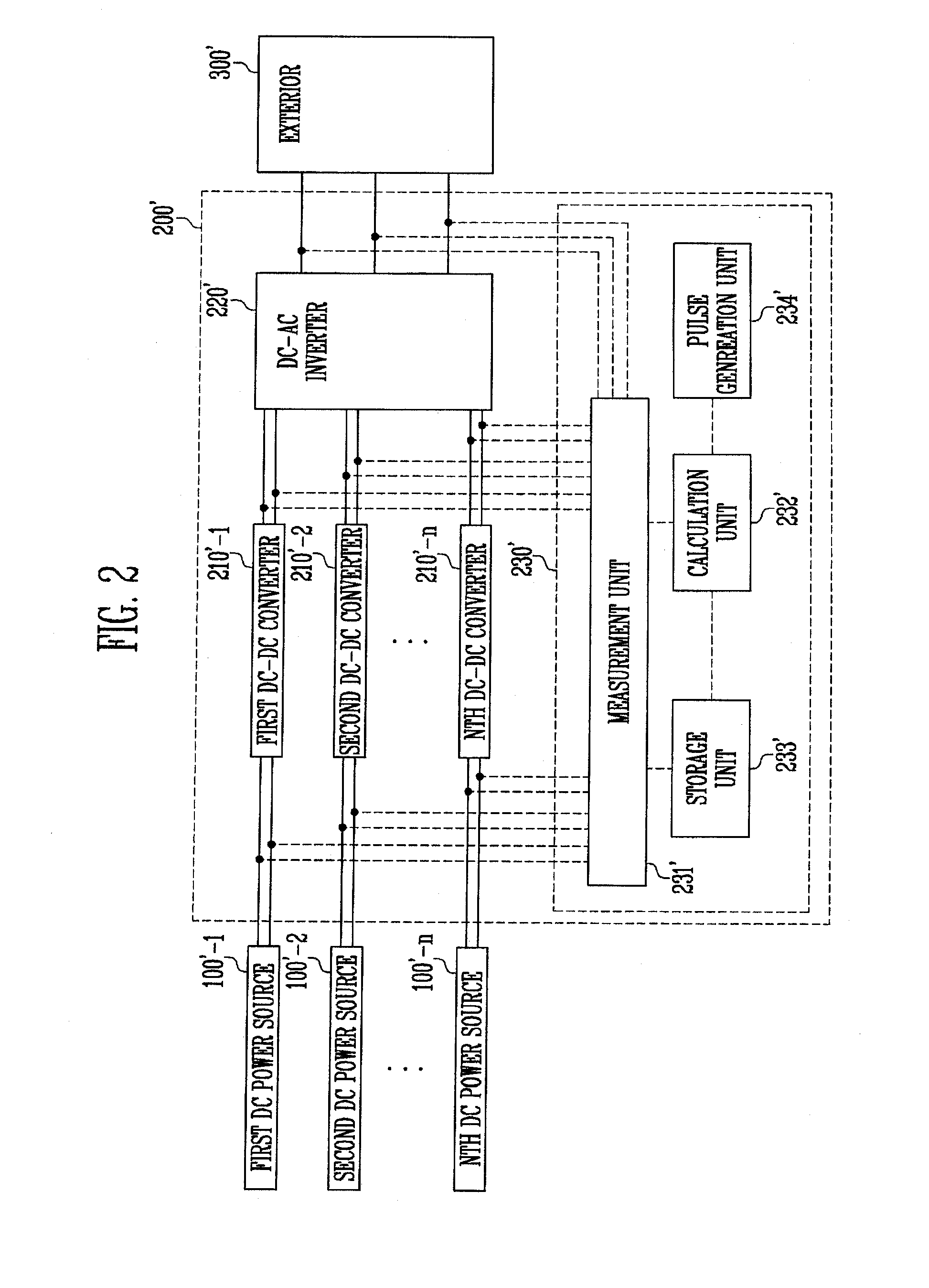
[0016]A level of a first carrier frequency used for PWM of a first DC-DC converter receiving first power, among the plurality of DC-DC converters, may be determined in the determining the levels of carrier frequencies of the some the plurality of DC-DC converters, and the determining of the levels of carrier frequencies of some of the plurality of DC-DC converters may include: supplying only first converted power from the first DC-DC converter to the DC-AC inverter; setting the level of the first carrier frequency of the first DC-DC converter to an initial level; when driving is performed with the first carrier frequency having the initial level, measuring a conversion efficiency of first power, defined as a ratio of power provided by the DC-AC inverter to the first power; and storing the conversion efficiency of first power and the initial level of the first carrier frequency, as a maximum conversion efficiency of the first power and an optimal carrier frequency level, respectively, wherein the storing of the conversion efficiency of first power and the initial level of the first carrier frequency, as the maximum conversion efficiency of the first power and the optimal carrier frequency level, respectively, is performed only when the optimal carrier frequency level has not been stored or the conversion efficiency of the first power is greater than the maximum conversion efficiency of the first power.
[0017]The determining of the levels of the carrier frequencies of the some of the plurality of DC-DC converters may further include: setting the level of the first carrier frequency to one of a plurality of levels for which conversion efficiency of the first power has not been measured, wherein, in the setting of the level of the first carrier frequency of the first DC-DC converter to the initial level, the initial level is a lowest level among levels that the first carrier frequency may have, and in the setting of the level of the first carrier frequency to one of levels for which conversion efficiency of the first power has not been measured, the level of the first carrier frequency is set to the lowest level among levels that the first carrier frequency may have but for which conversion efficiency of the first power has not been measured.
[0018]The determining of the level of the DC-AC carrier frequency may include: setting the level of the DC-AC carrier frequency to an initial level; when driving is performed with the DC-AC carrier frequency having the initial level, measuring a conversion efficiency of total power defined as a ratio of power provided by the DC-AC inverter to a sum of powers supplied to the power conversion device; and storing the conversion efficiency of total power and the initial level of the DC-AC carrier frequency as a maximum conversion efficiency of the total power and an optimal carrier frequency level, respectively, wherein the storing of the conversion efficiency of total power and the initial level of the DC-AC carrier frequency, as the maximum conversion efficiency of the total power and the optimal carrier frequency level, respectively, is performed only when the optimal carrier frequency level has not been stored or the conversion efficiency of the total power is greater than the maximum conversion efficiency of the total power.
[0019]The determining of the level of the DC-AC carrier frequency may further include: setting a level of a DC-AC dead time used by the DC-AC inverter to an initial level; and setting the level of the DC-AC dead time as one of levels for which conversion efficiency of total power has not been measured, wherein, in the determining of the level of the DC-AC carrier frequency, the level of the DC-AC dead time is further determined.
[0020]According to aspects of embodiments of the present invention, in a power conversion device and the method of driving the same, because a carrier frequency may be determined at every predetermined period, even though a component of the power conversion device is aged or replaced, a frequency maximizing power conversion efficiency may be determined again to thus actively cope with the corresponding situation.

Problems solved by technology

However, when an optimal carrier frequency of a power conversion device is changed due to aging or replacement of a component of the power conversion device with the passage of time, it may not be possible to actively cope with the corresponding situation by changing the predetermined carrier frequency.

Method used


Image

  • Power conversion device and method of driving the same
  • Power conversion device and method of driving the same
  • Power conversion device and method of driving the same

Examples


Embodiment Construction

[0031]Hereinafter, example embodiments of the present invention will be described in more detail with reference to the accompanying drawings. Throughout the specification, the like reference numerals denote the substantially same elements. In describing the present invention, if a detailed explanation for a related known function or construction is considered to unnecessarily divert the gist of the present invention, such explanation may be omitted but would be understood by those skilled in the art. Names of elements used in the following description are selected for the purpose of description and may be different from those of actual products.

[0032]The present invention may be embodied in various different forms, and should not be construed as being limited to only the illustrated embodiments herein. Rather, these embodiments are provided as examples so that this disclosure will be thorough and complete, and will fully convey the aspects and features of the present invention to th...


PUM


Abstract

A power conversion device includes: a first DC-DC converter configured to receive a first power from a first DC power source and to convert at least one of a voltage level and a current level to generate a first converted power; a DC-AC inverter electrically coupled to the first DC-DC converter and configured to convert the first converted power into a first AC power and to provide the first AC power to an external device; and a control unit configured to control the first DC-DC converter and the DC-AC inverter, wherein the first DC-DC converter and the DC-AC inverter are configured to be driven according to pulse width modulation (PWM) scheme using a first carrier frequency and a DC-AC carrier frequency, respectively, wherein a level of the first carrier frequency and a level of the DC-AC carrier frequency are determined according to predetermined time periods.

Description

CROSS-REFERENCE TO RELATED APPLICATION[0001]This application claims priority to and the benefit of Korean Patent Application No. 10-2015-0021128, filed on Feb. 11, 2015, in the Korean Intellectual Property Office, the entire content of which is incorporated herein by reference in its entirety.BACKGROUND[0002]1. Field[0003]The present invention relates to a power conversion device and a method of driving the same.[0004]2. Description of the Related Art[0005]A power conversion device receiving direct current (DC) power and providing alternating current (AC) power has been studied, and research for increasing a level of provided AC power compared with a level of supplied DC power has been conducted. For example, in case of a power conversion device driven according to a pulse width modulation (PWM) scheme using a carrier frequency, an attempt to increase power conversion efficiency using a carrier frequency set in consideration of power consumption efficiency has been made.[0006]Howeve...

Claims


Application Information

Patent Timeline
Patent Type & Authority Applications(United States)
IPC IPC(8): H02J3/00H02M7/44H02M3/04
CPCH02J3/00H02M7/44H02M3/04H02J1/102
Inventor HAN, SANGTAEKSTANISLAV, PRYKHODKO
Owner SAMSUNG SDI CO LTD
Why Eureka
Try Eureka