Antenna impedance tuner

a technology of impedance tuning and antenna node, applied in the direction of resonant circuit tuning, discontnuous tuning with seperate pre-tuned circuits, electrical devices, etc., can solve the problems of antenna node being susceptible to a mismatched impedance, power transmission efficiency degradation, and significant difference in actual impedan

Active Publication Date: 2019-08-15
SKYWORKS SOLUTIONS INC
View PDF2 Cites 9 Cited by
  • Summary
  • Abstract
  • Description
  • Claims
  • Application Information

AI Technical Summary

Problems solved by technology

However, the antenna and / or the related antenna feedline may present an actual impedance that is significantly different than the desired impedance.
In such a situation, power transmission efficiency becomes degraded.
The signal node can have a matched impedance, and the antenna node can be susceptible to a mismatched impedance.

Method used


Image

  • Antenna impedance tuner
  • Antenna impedance tuner
  • Antenna impedance tuner

Examples


Embodiment Construction

[0080]The headings provided herein, if any, are for convenience only and do not necessarily affect the scope or meaning of the claimed invention.

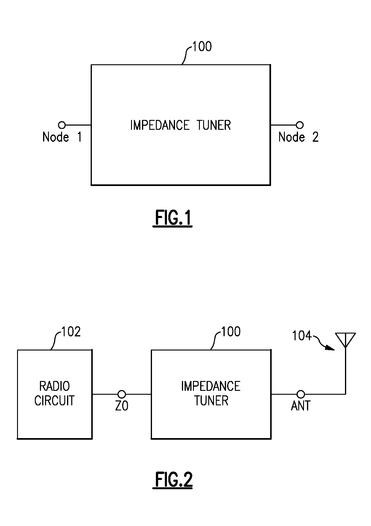
[0081]In wireless devices such as mobile units, an impedance presented by an antenna to a radio circuit can vary with, for example, environmental changes. To maintain the best or acceptable impedance match between the radio circuit and the antenna, an impedance tuner can be implemented. Such an impedance tuner, typically inserted between the radio circuit and the antenna, can include a tunable inductor-capacitor (LC) network and be adjusted as needed when a mismatch in impedance is detected.

[0082]In many applications, such impedance circuits can be costly and / or be limited in tuning range capability. For example, in some embodiments, a tuner can include a single switchable element, either in series or in shunt relative to a signal path, resulting in two impedance tuning states.

[0083]In another example, a complex PI-network can be implemente...


PUM


Abstract

An antenna impedance tuner can include first and second nodes, a bypass path, first and second series capacitance paths, and an inductance path, with each path being implemented between the first and second nodes and including a switch configured to allow the path to couple or uncouple the first and second nodes. The tuner can further include first and second shunt paths, with each shunt path being implemented between the second node and ground and including a switch configured to allow the shunt path to couple or uncouple the second node and the ground. The tuner can further include a switchable grounding path implemented along the inductance path and configured to allow the inductance path to function as a series inductance path between the first and second nodes, or as a shunt inductance path between the ground and a node along the inductance path.

Description

CROSS-REFERENCE TO RELATED APPLICATION(S)[0001]This application claims priority to U.S. Provisional Application No. 62 / 629,570 filed Feb. 12, 2018, entitled ANTENNA IMPEDANCE TUNER, the disclosure of which is hereby expressly incorporated by reference herein in its respective entirety.BACKGROUNDField[0002]The present disclosure relates to antenna impedance tuning circuits and related devices and methods.Description of the Related Art[0003]In radio-frequency (RF) applications, power transfer is improved for a signal when impedance is matched between two components encountered by the signal. For example, when a signal is generated by a radio circuit and sent to an antenna for transmission, it is desirable to have as much of the signal's power be delivered to the antenna.[0004]In the foregoing antenna-transmission example, the radio circuit is typically designed to maximize power transfer when the antenna provides a desired impedance. However, the antenna and / or the related antenna fee...

Claims


Application Information

Patent Timeline
Patent Type & Authority Applications(United States)
IPC IPC(8): H04B1/04H04B1/18H03H7/40
CPCH04B1/0458H04B1/18H03H7/40H03H2007/386H03H7/38H03J2200/06H03J1/0008H03J5/24
Inventor DOMINO, WILLIAM J.
Owner SKYWORKS SOLUTIONS INC
Why Eureka
Try Eureka