Leg undercarriage system for jumping aircraft

a technology of undercarriage system and aircraft, which is applied in the direction of aircraft components, transportation and packaging, and light gear, etc., can solve the problems of reducing the range of flight, reducing the efficiency of landing, and reducing the ability of fixed wing aircraft to perform standing takeoffs or spot landings, so as to achieve the effect of imparting velocity and altitude to the aircraft and saving propelling energy

Inactive Publication Date: 2019-09-05
PASSERINE AIRCRAFT CORP
View PDF0 Cites 0 Cited by
  • Summary
  • Abstract
  • Description
  • Claims
  • Application Information

AI Technical Summary

Benefits of technology

[0007]Embodiments of the invention may include an attachment to an aircraft fuselage and one or more leg links and a foot in contact with the ground. A power spring may store energy for propelling the aircraft. A quick release hook may hold the leg undercarriage in a prelaunch position. An actuation source may move the aircraft to a position that triggers the quick release hook to release and cause the power spring to release its energy and quickly transition the leg undercarriage system to a fully extended state. This may impart velocity and altitude to the aircraft.

Problems solved by technology

The requirement of a runway for takeoff and landing limits the situations in which fixed wing aircraft can operate.
They cannot perform standing takeoffs or spot landings.
However, they have several disadvantages as compared to fixed wing aircraft such as less endurance, lower flight speed, shorter range, and less scalability.

Method used


Image

  • Leg undercarriage system for jumping aircraft
  • Leg undercarriage system for jumping aircraft
  • Leg undercarriage system for jumping aircraft

Examples


Embodiment Construction

[0021]For clarity in explanation, the invention has been described with reference to specific embodiments, however it should be understood that the invention is not limited to the described embodiments. On the contrary, the invention covers alternatives, modifications, and equivalents as may be included within its scope as defined by any patent claims. The following embodiments of the invention are set forth without any loss of generality to, and without imposing limitations on, the claimed invention. In the following description, specific details are set forth in order to provide a thorough understanding of the present invention. The present invention may be practiced without some or all of these specific details. In addition, well known features may not have been described in detail to avoid unnecessarily obscuring the invention.

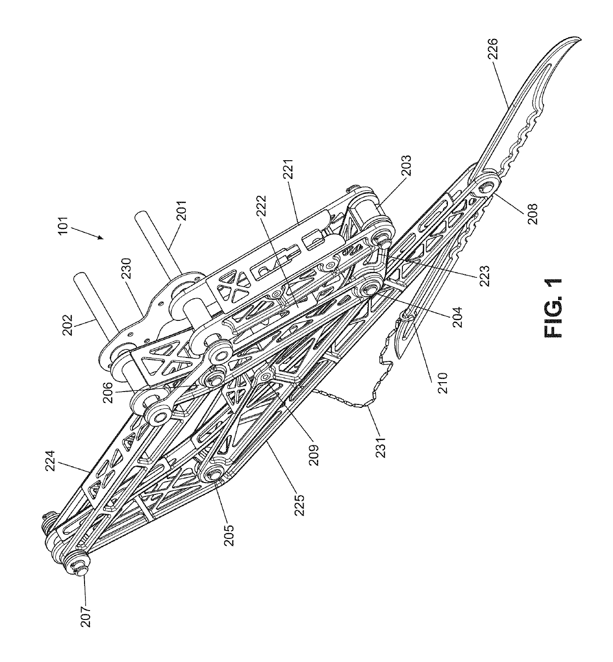
[0022]FIG. 1 is perspective view of one leg 101 of a leg undercarriage system 1101 that is a landing gear for an aircraft. The leg undercarriage system ma...


PUM


Abstract

Methods and systems are provided to allow a traditional fixed wing aircraft to perform standing takeoffs and spot landings. Methods and systems relate to a leg undercarriage system that allow an aircraft to take off from a stationary position and to make a spot landing. Methods and systems include an attachment to an aircraft fuselage and one or more leg links and a foot in contact with the ground, a power spring to store energy for propelling the aircraft, a quick release hook to hold the leg undercarriage in a prelaunch position, and an actuation source to move the aircraft to a position that triggers the quick release hook to release and cause the power spring to release its energy and quickly transition the leg undercarriage system to a fully extended state, thus imparting velocity and altitude to the aircraft. Methods and systems relate to a retraction spring for retracting the leg undercarriage system to a flight position and an electrical servo for retracting the leg undercarriage system to a flight position.

Description

CROSS-REFERENCE TO RELATED APPLICATIONS[0001]This application claims the benefit of U.S. Provisional Patent Application No. 62 / 638,114 filed Mar. 3, 2018, which is / are all hereby incorporated by reference in their entirety.FIELD OF THE INVENTION[0002]The present invention relates to a leg undercarriage system for propelling an aircraft into the air.BACKGROUND[0003]Traditional fixed wing aircraft take off by accelerating and rolling on a runway and nosing up for takeoff. The requirement of a runway for takeoff and landing limits the situations in which fixed wing aircraft can operate. They cannot perform standing takeoffs or spot landings.[0004]Rotor aircraft such as helicopters can take off without specific takeoff or landing infrastructure. However, they have several disadvantages as compared to fixed wing aircraft such as less endurance, lower flight speed, shorter range, and less scalability.[0005]It would be desirable to develop mechanisms for a traditional fixed wing aircraft t...

Claims


Application Information

Patent Timeline
Patent Type & Authority Applications(United States)
IPC IPC(8): B64C25/00
CPCB64C2025/008B64C25/001
Inventor WHALLEY, MATTHEW
Owner PASSERINE AIRCRAFT CORP
Why Eureka
Try Eureka