Naval platform provided with a deck landing/take-off zone and means for handling an aircraft

Active Publication Date: 2019-09-05
NAVAL GRP
View PDF10 Cites 0 Cited by
  • Summary
  • Abstract
  • Description
  • Claims
  • Application Information

AI Technical Summary

Benefits of technology

The invention relates to a vessel platform that can handle aircraft on a deck landing / takeoff zone. The platform has a gripping and securing bar for the main landing gear of the aircraft, which can slide into a rail and be retracted for easy release and positioning. The platform also has maneuvering means for moving and securing the aircraft, including a lever and visual indicators for the hook-type means. The platform can be equipped with a harpoon grate and a storage hangar for the aircraft, and includes motorized trucks for grasping the auxiliary landing gear of the aircraft. Overall, the invention allows for safe and efficient handling of aircraft on a deck landing / takeoff zone.

Problems solved by technology

However, these industrial truck means have a certain number of drawbacks, in particular in the considered application on board such a naval platform.
The platform is then subject to relatively significant movements, reflected by risks of uncontrolled movements / displacements of the aircraft on the platform and more particularly on the landing / take off zone.
The aircraft may in fact undergo forces causing total or partial slippage, or even tilting thereof.
Another problem appears in light of the current size of the landing / takeoff zones and the aircraft intended for these platforms.
Indeed, helicopters are increasingly large and the zones are tending to become smaller, which requires maneuvering these aircraft multiple times, applying increasingly large and frequent stresses on the structures thereof.
Yet the structure of these aircraft has not always been sized to withstand such handling.
Lastly, the aircraft generally sets down in different locations each time and may even be set down in a location of the zone that is difficult to access in complete safety.

Method used


Image

  • Naval platform provided with a deck landing/take-off zone and means for handling an aircraft
  • Naval platform provided with a deck landing/take-off zone and means for handling an aircraft
  • Naval platform provided with a deck landing/take-off zone and means for handling an aircraft

Examples


Embodiment Construction

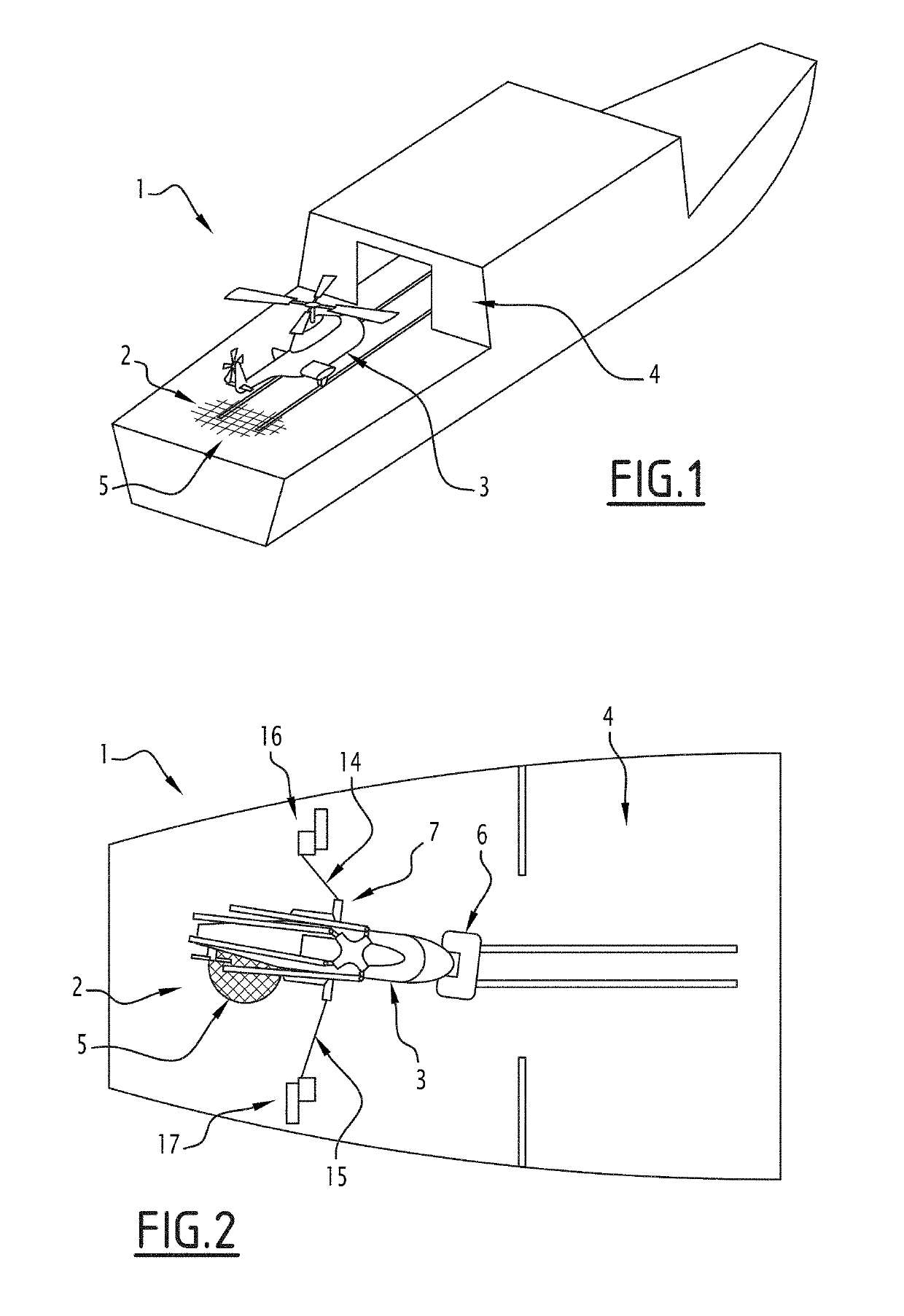
[0040]In these figures, and in particular in FIG. 1, a naval platform is illustrated and designated by general reference 1.

[0041]In the example embodiment illustrated in this FIG. 1, the naval platform 1 is made up of a surface building, such as a corvette or a frigate.

[0042]Of course and as previously indicated, other examples of platforms can be considered.

[0043]In the described example, the naval platform 1 therefore includes, in its rear part, a deck landing / takeoff zone, designated by general reference 2, for an aircraft, designated by general reference 3, made up, in the described example, of a rotary-wing aircraft such as a helicopter.

[0044]Other types of aircraft may be considered.

[0045]Likewise, drones may be considered.

[0046]The platform 1 is also provided, in the described example, with a storage hangar 4 for this type of aircraft and for example this helicopter, near this deck landing / takeoff zone 2.

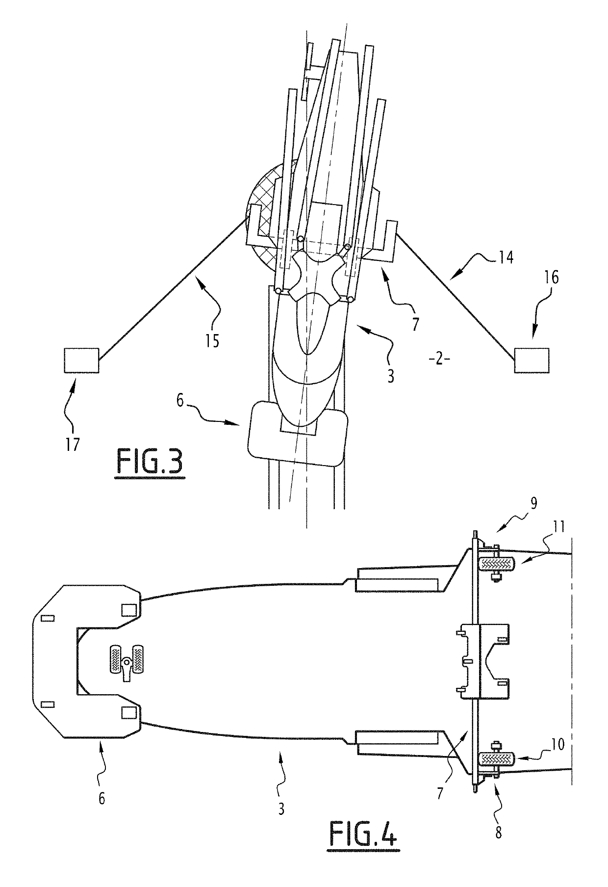
[0047]It will also be noted that the deck landing / takeoff zone 2 of the ...


PUM


Abstract

A naval platform has a zone for the deck landing / take-off of an aircraft and an aircraft handler, to move the aircraft over the deck landing / take-off zone. The aircraft handler includes a body in the form of a bar for gripping and securing the main landing gear of the aircraft, provided with an anchoring hook mounted to slide in at least one rail, guiding the the aircraft on the deck landing / take-off zone. The hook is retractable, allowing the release of the body in the form of a gripping and securing bar from the rail, the body gripping the landing gear of the aircraft. The movement of the aircraft brings the body into position on the rail, and the hook into a position in which it faces the rail, and the hook back into an anchoring position in the rail in order to secure the aircraft.

Description

BACKGROUND OF THE INVENTIONField of the Invention[0001]The present invention relates to a naval platform.[0002]More specifically, the invention relates to a naval platform equipped with a landing / takeoff zone for at least one aircraft.Description of the Related Art[0003]Such naval platforms are for example made up of surface vessels such as corvettes, frigates or projection buildings, or even aircraft carriers.[0004]Of course, other platforms, such as offshore oil platforms or the like, equipped with zones intended to receive helicopters, can also be considered.[0005]Traditionally, these platforms are also equipped with means in truck form, for example with motors, for handling the aircraft to move it on the platform.[0006]Thus for example, and in the case where the platform is made up of a vessel such as a corvette or a frigate, such industrial truck means are used for example to move a helicopter, between the landing / takeoff zone of the platform and a storage hangar thereof, provi...

Claims


Application Information

Patent Timeline
IPC IPC(8): B64F1/12B64F1/22
CPCB64F1/22B64F1/125B63B35/50
Inventor BAURY, ALEXANDRERASPIC, PIERREPERILLAUD, JERÔME
Owner NAVAL GRP
Why Eureka
Try Eureka