Battery pack with two end plates

a battery pack and end plate technology, applied in secondary cell servicing/maintenance, battery components, cell components, etc., can solve the problems of increasing the design difficulty of the battery pack, the inability of existing dc power sources to meet the higher requirements of the newly designed, and the inability to design the battery pack. to achieve the effect of limiting the expansion prolonging the service life of the battery cell, and facilitating the mounting of the battery cell

Active Publication Date: 2019-09-05
CLARIOS ADVANCED POWER SOLUTIONS GMBH +1
View PDF1 Cites 5 Cited by
  • Summary
  • Abstract
  • Description
  • Claims
  • Application Information

AI Technical Summary

Benefits of technology

[0039]The battery pack provided by the present disclosure has two end plates located at two sides of the battery cells, respectively. In addition to bearing the electronic components and connecting a circuit, the two end plates also play a role of supporting the multiple battery cells to facilitate mounting the battery cells and provide a certain pressure against the battery cells thereby to limit expansion of the battery cells within a certain extent and prolong the service life of the battery cells; moreover, they may deform to absorb expansion of the battery cells to enable the housing of the entire battery pack to maintain unchanged.

Problems solved by technology

The newly design hybrid vehicles' high requirements above on the DC power source make battery pack design more difficult.
These requirements make it even more difficult to design the battery pack.
The existing DC power sources often cannot meet the higher requirements of the newly designed hybrid vehicles on the DC power source.

Method used


Image

  • Battery pack with two end plates
  • Battery pack with two end plates
  • Battery pack with two end plates

Examples


Embodiment Construction

below with reference to the drawings. Throughout the drawings, identical reference numerals represent identical components, wherein:

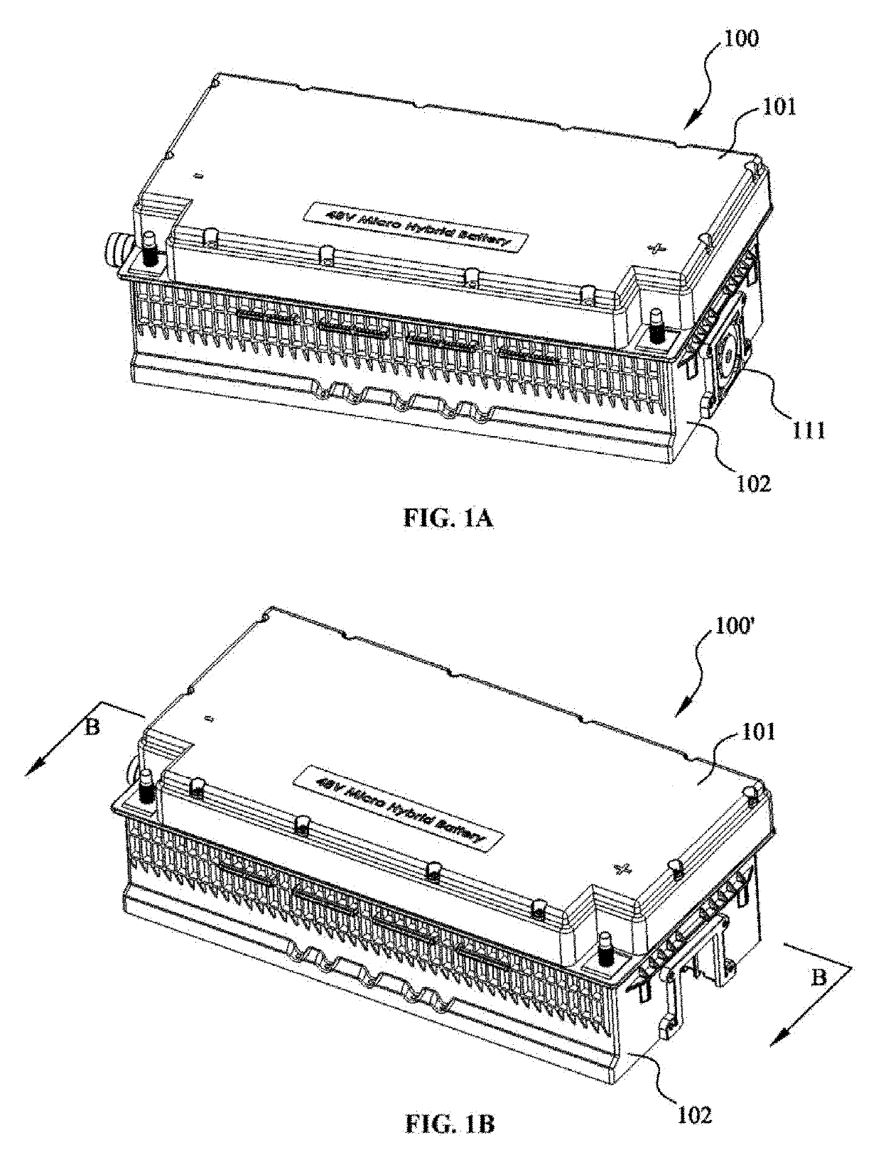
[0041]FIG. 1A is a schematic diagram of a battery pack according to the present disclosure, in which a fan is mounted;

[0042]FIG. 1B is a schematic diagram of a battery pack without mounting a fan according to the present disclosure;

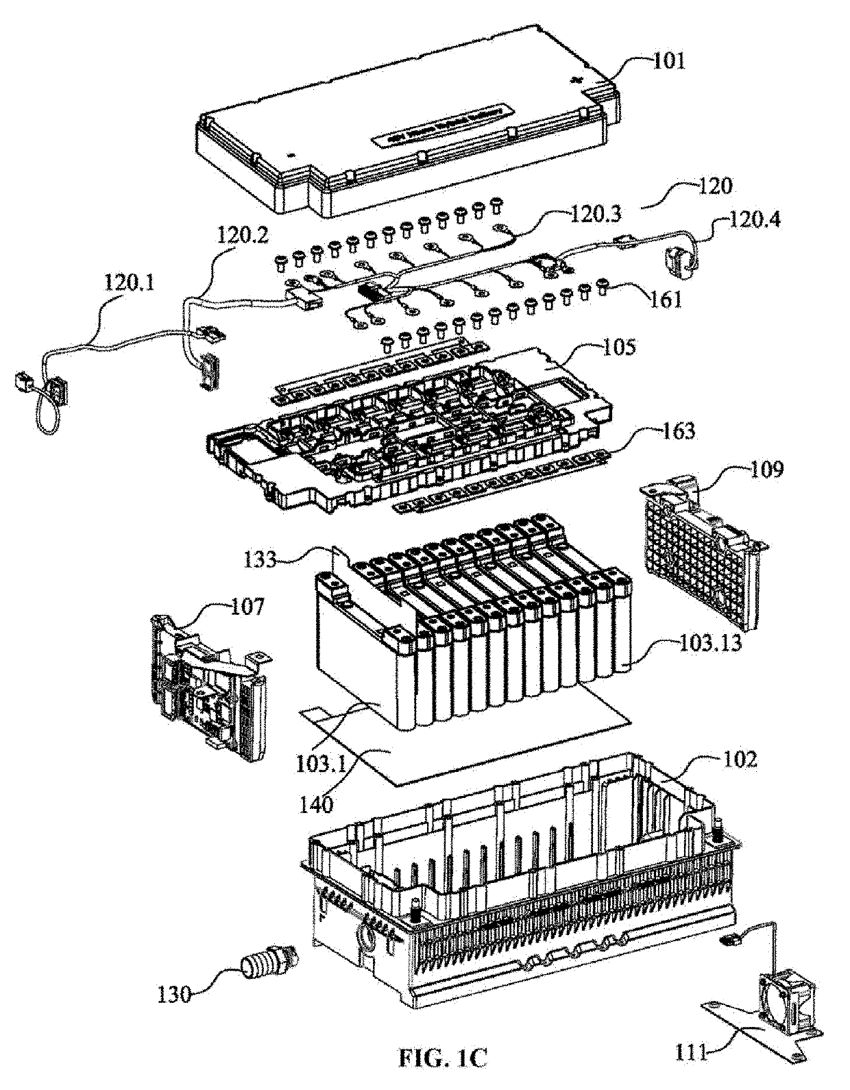
[0043]FIG. 1C is an exploded schematic view of the battery pack in FIG. 1A;

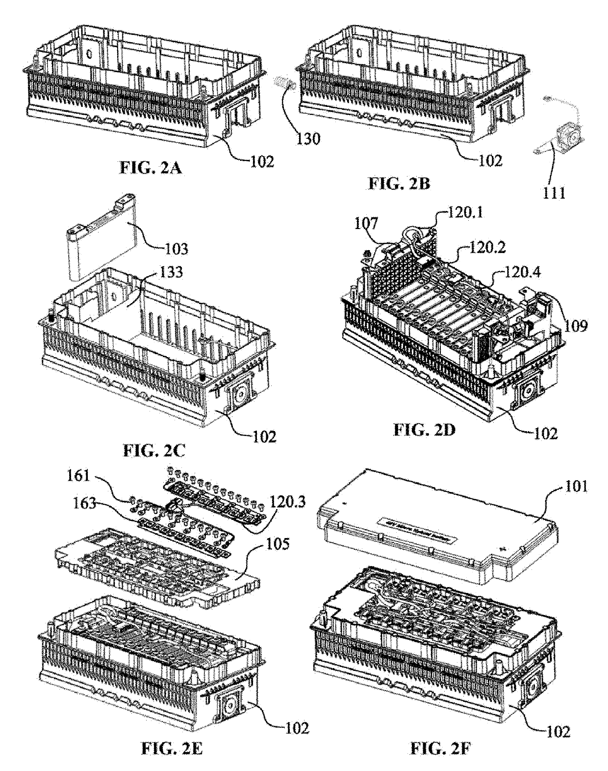
[0044]FIGS. 2A-F are schematic diagrams of the mounting process of the battery pack shown in FIG. 1A;

[0045]FIG. 3 is a stereoscopic view of a battery cell in a battery pack according to the present disclosure;

[0046]FIG. 4A is a stereoscopic schematic view of a housing of a battery pack according to the present disclosure;

[0047]FIG. 4B is a top schematic view of the housing of the battery pack according to the present disclosure;

[0048]FIG. 5A is a stereoscopic schematic view of a bearing plate of a battery pack according to the present disclosure;

[0049]...


PUM

PropertyMeasurementUnit
DC voltageaaaaaaaaaa
deformation displacementaaaaaaaaaa

Abstract

The present disclosure provides a battery pack including a housing, wherein the housing has a bottom portion and side walls extending upward around a periphery of the bottom portion; an upper portion opening is formed at top ends of the side walls extending upward; an upper cover is mounted on the upper portion opening of the housing; and the battery pack comprises: multiple flat battery cells; and a first end plate and a second end plate, wherein when the multiple battery cells are sequentially arranged and mounted into the housing from the upper portion opening, the first end plate and the second end plate are located at two end sides of the sequentially arranged multiple battery cells to laterally fix the sequentially arranged multiple battery cells. The two end plates may absorb deformation of the battery cell while expanding.

Description

TECHNICAL FILED[0001]The present disclosure generally relates to a battery pack comprised of a plurality of battery cells, and more particularly to a battery pack having two end plates and comprising a plurality of serially-connected battery cells for a hybrid vehicle.BACKGROUND[0002]To improve fuel efficiency, in addition to enhance efficiency of a traditional gasoline engine, a hybrid vehicle also can use a battery pack comprised of a plurality of serially-connected battery cells as a DC power source providing a certain voltage for an electric motor to help driving the hybrid vehicle. For example, by serially connecting 13 battery cells each having a 3.65V DC voltage, a battery pack having a 48V DC voltage may be formed as a DC power source providing the 48V DC voltage.[0003]Constant development of hybrid vehicles sets a higher requirement on the DC power source. For example, newly designed hybrid vehicles are equipped with some parts that require a larger driving current, includi...

Claims


Application Information

Patent Timeline
Patent Type & Authority Applications(United States)
IPC IPC(8): H01M2/10H01M10/42H01M50/209H01M50/242H01M50/249H01M50/262H01M50/271H01M50/284H01M50/289H01M50/296H01M50/35H01M50/583
CPCH01M2/1077H01M2220/20H01M2010/4271H01M10/425H01M50/271H01M50/242H01M50/284H01M50/583H01M10/482H01M50/296H01M50/209H01M50/289H01M50/262H01M50/35H01M2200/103Y02E60/10H01M50/3425
Inventor FU, YINGYAOFAN, BINBINLIU, CHANGWIEGMANN, MARTINBIRKHOLZ, JOERGJENSEN, MARCOZHANG, XUGANGCZARNECKI, JENNIFER L.
Owner CLARIOS ADVANCED POWER SOLUTIONS GMBH
Why Eureka
Try Eureka