Double tube immersion electronic circulation cooking device

a technology of electronic circulation and cooking device, which is applied in the direction of multi-unit cooking vessel, water bath cooking vessel, kitchen equipment, etc., can solve the problems of inability to quickly thaw and/or cook more than one food

Active Publication Date: 2019-09-12
PUC PERFECT UNION
View PDF3 Cites 3 Cited by
  • Summary
  • Abstract
  • Description
  • Claims
  • Application Information

AI Technical Summary

Benefits of technology

[0005]It is therefore one object of the invention to provide a circulation cooking device comprising a housing including a front member having two spaced front shells, and a rear member having two spaced rear shells wherein two opening members are formed on each front shell, two first recesses are formed on an underside of each front shell, a half circular first groove is formed on a joining portion of the first recesses and the underside of each front shell, a circuit board and an LCD (liquid-crystal display) display are disposed in the opening members respectively, and a transparent touchscreen is disposed on the opening members; and each rear shell includes a top opening, a plurality of lower openings, a plurality of upper openings, two second recesses formed on an underside, and a half circular second groove formed on a joining portion of the second recesses and the underside of each rear shell; two cylindrical casings detachably secured to the housing, each casing including a plurality of projections on an inner surface of an upper portion configured to dispose in the corresponding recesses, a vertical opening, and a plurality of horizontal openings; two inlet devices each mounted to a bottom of the casing and including a plurality of inlets; two sets each comprising a wheel control device disposed in the housing and including a wheel and a hollow fastening member with the wheel projecting out of its open top and further projecting out of the top opening; a temperature limiting thermostat disposed in the housing and including a temperature probe; a mechanical fan for drawing cold air from the lower openings and expelling hot air out of the housing via the upper openings; a main circuit board disposed in the housing and configured to activate heating and agitation; a circuit board for switch control being further configured to control the main circuit board: a drive source for agitation and testing disposed in the housing and including a motor, a motor shaft extending downward from the motor, and two probes for sensing temperature and for measuring water level respectively; a support for heating member disposed on a bottom of the housing and including an annular flange positioned in the first and second grooves seal the bottom of the housing; an electric heating member disposed in the casing and extending downward from the flange wherein the motor shaft, the probes for sensing temperature and for measuring water level, and the temperature probe pass the support for heating member to be proximate the electric heating member and wherein the temperature probe and the electric heating member are fastened together; a fan blade assembly fastened at a bottom end of the motor shaft and under the electric heating member; a ground having one end connected to the electric heating member; and two AC (alternating current) power cords each having one end passing through the rear shell to electrically connect to the main circuit board for supplying power thereto; and a seat for double, container including two spaced circular brackets, two flexible mounts extending downward from en intermediate portion between the brackets, a top cavity between the brackets, and a snapping member having two top latches and a plurality of ribs on either side wherein the snapping member is positioned between the mounts with the latches fastened in the cavity, the seat for double container is configured to mount onto two containers with each mount urging against an inner surface of the container and the ribs urging against an outer surface of each container, and the casings are inserted through the brackets to dispose in the containers.

Problems solved by technology

It is impossible of quickly thawing and / or cooking more than one food.

Method used


Image

  • Double tube immersion electronic circulation cooking device
  • Double tube immersion electronic circulation cooking device
  • Double tube immersion electronic circulation cooking device

Examples


Embodiment Construction

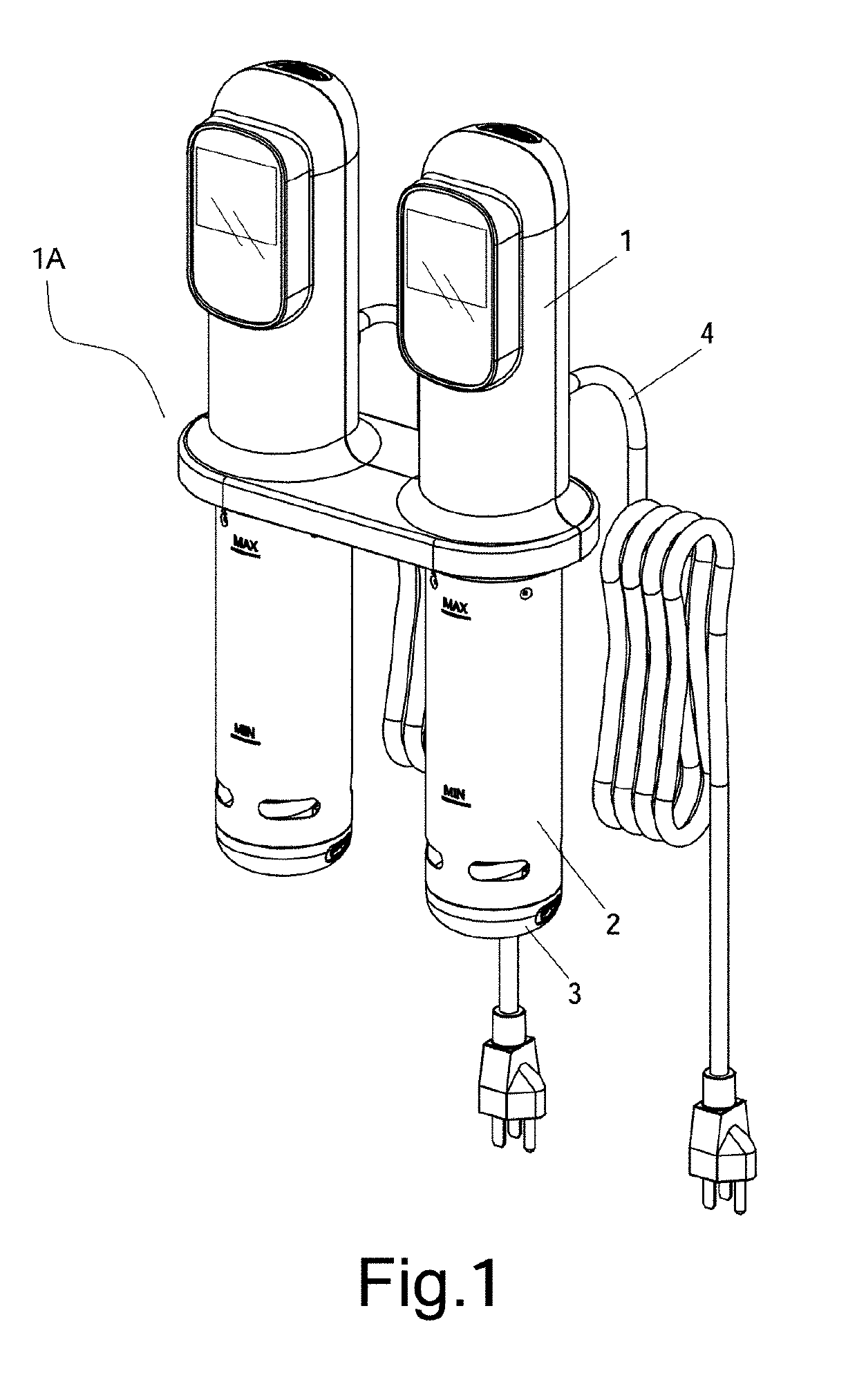
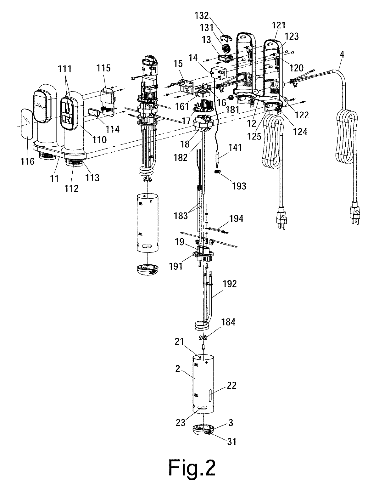
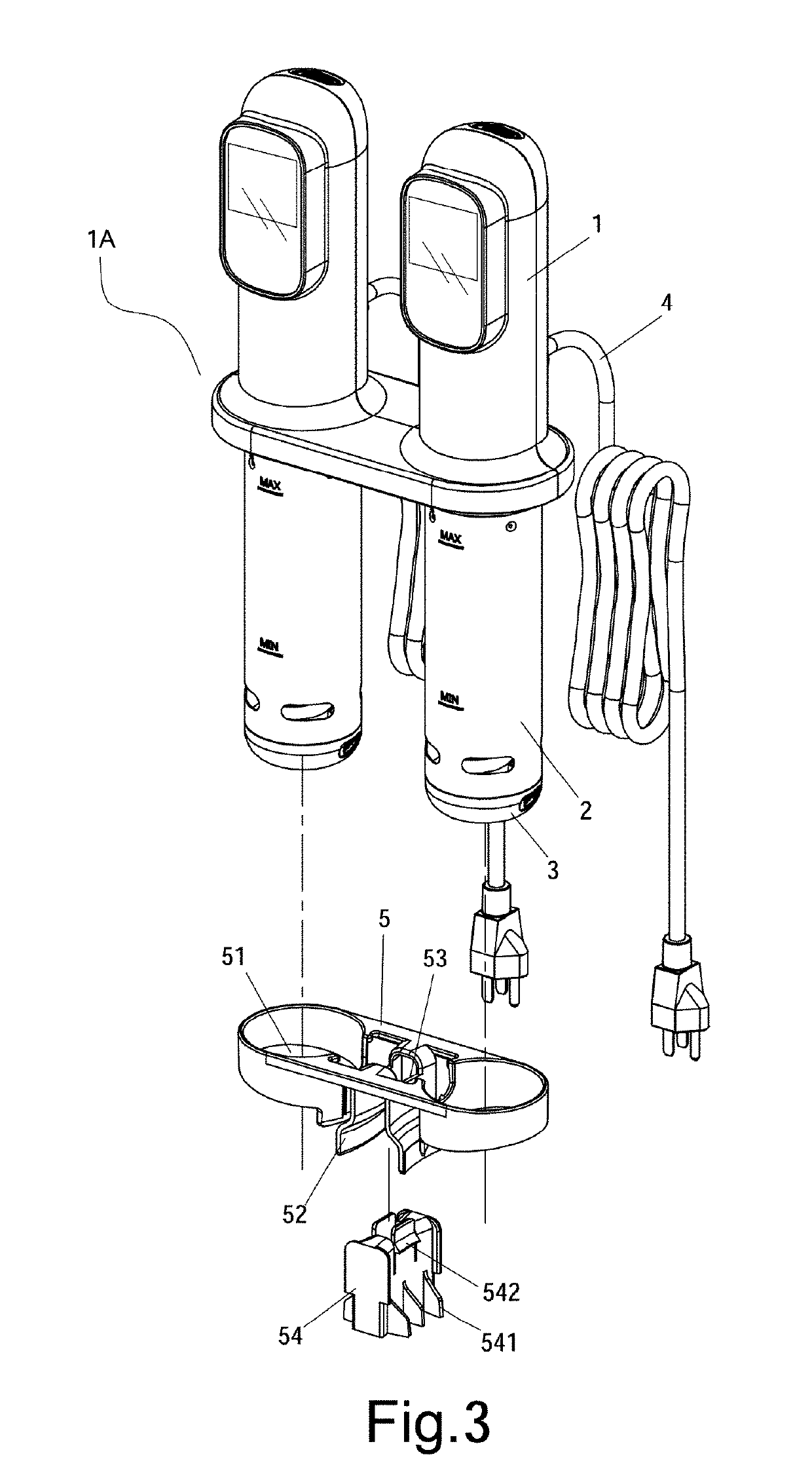
[0015]Referring to FIGS. 1 and 2, a double tube immersion electronic circulation cooking device 1 A in accordance with the invention comprises the following components as discussed in detail below.

[0016]A housing 1 includes a front member 11 having two spaced front shells 110 and a rear member 12 having two spaced rear shells 120. The front member 11 and the rear member 12 are detachably secured together to form the housing 1 having an internal space. Two openings 111 are formed on a front surface of the front shell 110. Two recesses 112 are formed on an underside of the front shell 110 and a half circular groove 113 is formed on a joining portion of the recesses 112 and the underside of the front shell 110. A circuit board 114 and an LCD (liquid-crystal display) display 115 are provided in the openings 111 respectively. A transparent touchscreen 116 is provided on the openings 111.

[0017]The rear shell 120 includes a top opening 121, a plurality of lower openings 122, a plurality of...


PUM


Abstract

A circulation cooking device includes a housing and two casings. Within the housing and the casings, there are provided two sets of a wheel control device, a temperature limiting thermostat, a circuit board for switch control, a mechanical fan for drawing cold air in and expelling hot air out, a main circuit board configured to activate heating and agitation; a drive source for agitation and testing, a support for heating member, an electric heating member, a fan blade assembly, and an inlet device. The circulation cooking device can mounted on a large container by a seat for single container or two small containers by a seat for double container.

Description

BACKGROUND OF THE INVENTION1. Field of the Invention[0001]The invention relates to food cooking devices and more particularly to a double tube immersion electronic circulation cooking device with improved characteristics.2. Description of Related Art[0002]Double tube is a method of cooking in which food is vacuum sealed in a plastic pouch and then placed in a water bath or steam environment for longer than normal cooking times, usually 1 to 7 hours, at an accurately regulated temperature much lower than normally used for cooking, typically around 55 to 60° C. for meat, higher for vegetables). The intent is to cook the item evenly, ensuring that the inside is properly cooked without overcooking the outside, and to retain moisture.[0003]Sous-vide circulation cooking devices are well known in the art. For example, US Publication Number 20160022085 A1 to Wu et al. discloses a sous-vide circulation cooking device for home sous-vide cooking. Also, US Publication Number 20160192801 A1 to W...

Claims


Application Information

Patent Timeline
Patent Type & Authority Applications(United States)
IPC IPC(8): A47J27/10A47J27/12A47J27/00A47J43/044A47J36/00
CPCA47J36/00A47J27/12A47J43/044A47J27/004A47J27/10
Inventor CHAN, CHING
Owner PUC PERFECT UNION
Why Eureka
Try Eureka