
Transportation Pathway And Method Of Forming Same

a transportation pathway and a technology of transportation pathways, applied in the direction of transportation and packaging, rail devices, transportation and packaging, etc., can solve the problems of complicated and uneven placement of metal sheets on surrounding ground, high cost, logistical complications, etc., to improve the performance characteristics of the pathway structure, facilitate turning, acceleration and braking, and increase the repulsion force

Active Publication Date: 2019-09-12
JASON AYOUB PTY LTD
View PDF0 Cites 3 Cited by
  • Summary
  • Abstract
  • Description
  • Claims
  • Application Information

AI Technical Summary

Benefits of technology

The patent describes a way to make a surface that can guide or direct objects above it, such as magnetic sources. This is done by using a liquid coating of conductive material that can deposit a continuous layer of conductive particles when dried. This liquid coating can be applied in different shapes and configurations to provide stability and motion control for the objects on top. The invention can be used to make a pathway for a moving vehicle or provide precision guidance for objects on the surface.

Problems solved by technology

The use of metal sheet material, even with holes cut out from it, can be very expensive as a way of providing a transportation pathway for a repulsion lift vehicle such as a hover engine.
It is admitted in the latter prior art document that a large amount of conductive material is required to form such a sheet substrate, which is costly as well as being complicated to evenly lay on surrounding ground.
Such additional requirements provide extra capital cost as well as logistical complications when constructing a transportation pathway for a repulsion lift vehicle.
In addition, the use of metal sheets necessitates laying a flat (or essentially planar) uppermost surface of pathway required for its use, which cannot easily be achieved when there are ground surface undulations.

Method used


Image

  • Transportation Pathway And Method Of Forming Same
  • Transportation Pathway And Method Of Forming Same
  • Transportation Pathway And Method Of Forming Same

Examples


Embodiment Construction

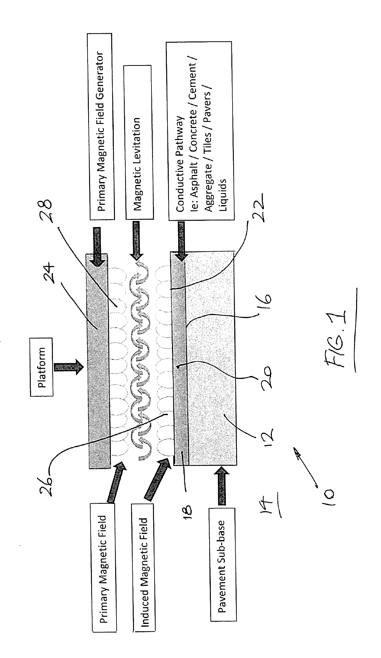
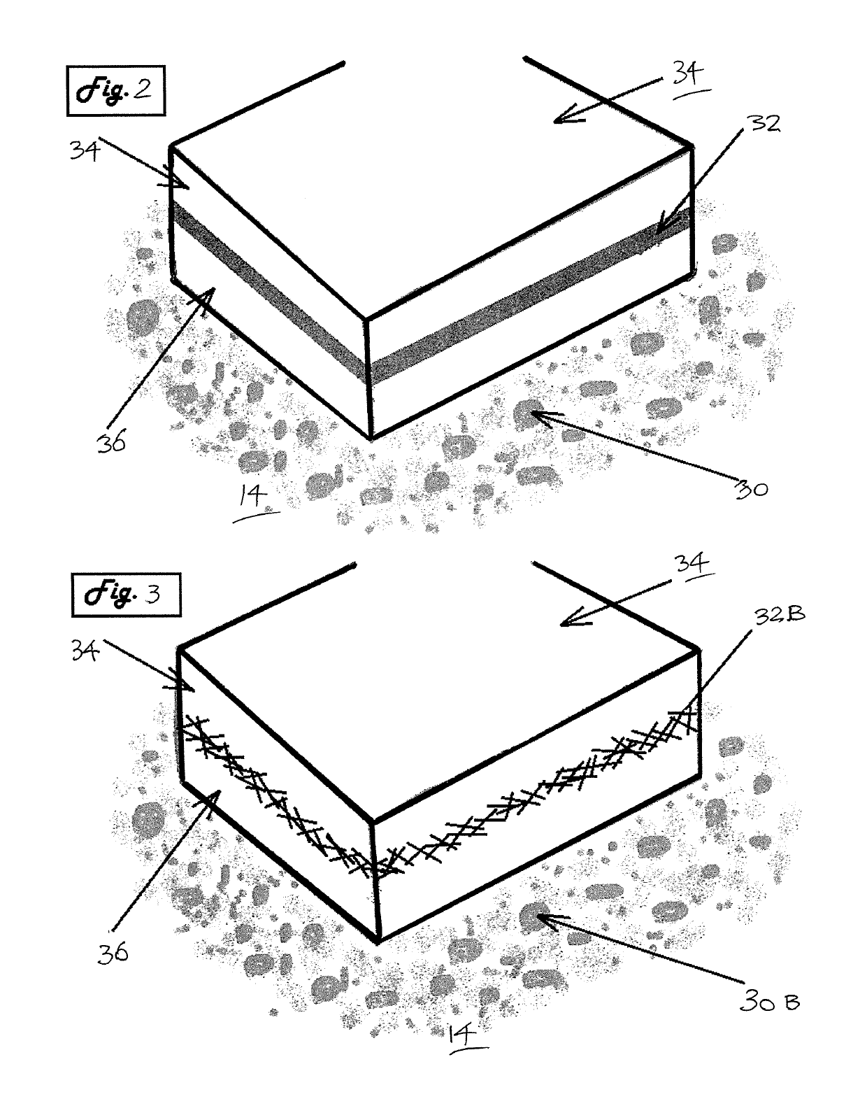
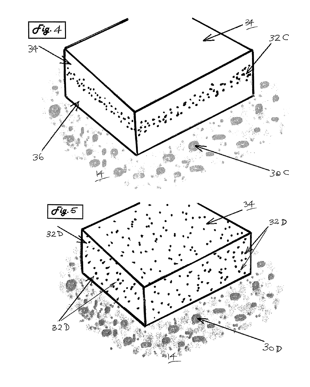
[0073]Referring to the drawings, and particularly to FIG. 1, an embodiment is disclosed of a transportation pathway in the form of a road 10, which comprises a pavement sub-base material 12 located at surrounding ground 14, which has a layer which includes a conductive material, in this example the layer being located on an uppermost surface 16 of the pavement sub-base 12. In the embodiment shown, the conductive material is in the form of a layer of asphalt 18 containing dispersed particulate conductive particles 20. However there are many other options for developing a conductive pathway, such as concrete, cement, aggregate, tiles, pavers and containing the conductive material, or even liquid conductive material which includes fine or colloidal conductive material, as will be described in the forthcoming examples. FIG. 17 summarises many of the possible ways which the conductive material may be added, and the many locations in which that conductive material can be arranged in the s...


PUM


Abstract

Embodiments are disclosed of a transportation pathway in the form of a road (10), which comprises a pavement sub-base material (12) located at surrounding ground (14), which has a layer which includes a conductive material. In one example, the layer is located on an uppermost surface (16) of the pavement sub-base (12). In the embodiment shown, the conductive material is in the form of a layer of asphalt (18) containing dispersed particulate conductive particles (20) in the form of graphene. A sufficient quantity of the conductive particles (20) is located a short depth from the uppermost road surface (22) of the asphalt layer (18), so that when the surface (22) is exposed to a primary magnetic field (28) generated by an external magnetic source positioned above the pathway, for example a powered hoverboard (24) or other vehicle, these conductive particles (20) create an induced magnetic field (26) which repels the primary magnetic field (28) being generated by the hoverboard (24). The opposing magnetic fields (26, 28) create a suspension of the hoverboard (24) above the road surface (22) known as magnetic levitation.

Description

TECHNICAL FIELD[0001]This disclosure relates generally to a transportation pathway and a method for forming a transportation pathway. While the present disclosure is mainly concerned with electromagnetic levitation systems, and more particularly to the method of forming a transportation pathway over which users can move devices which employ electromagnetic levitation, it can also be applied to the method of forming any type of route or access thoroughfare along which an object or a device can travel in a friction free manner. This can encompass within its meaning a distance over which objects other than vehicles can be moved, for example in manufacturing processes to move a component of machinery along a prescribed arc of movement, or a route over which a stream of items can be moved in a selected direction, for example in a conveyer system.BACKGROUND OF THE DISCLOSURE[0002]A known magnetic repulsion effect is associated with generating a moving magnetic field near a conductive obje...

Claims


Application Information

Patent Timeline
Patent Type & Authority Applications(United States)
IPC IPC(8): B60L13/04E01B25/30E01C9/00
CPCE01C9/00B60L13/04E01B25/30B60M7/00
Inventor AYOUB, JASON
Owner JASON AYOUB PTY LTD
Learn More