
Method for controlling power transmitting device, method for detecting foreign object, and power transmitting device in wireless power transmission system

a technology of wireless power transmission system and transmitting device, which is applied in the direction of rail devices, transportation and packaging, propulsion by batteries/cells, etc., can solve the problem that normal wireless charging cannot be performed

Active Publication Date: 2019-09-12
PANASONIC INTELLECTUAL PROPERTY MANAGEMENT CO LTD
View PDF2 Cites 4 Cited by
  • Summary
  • Abstract
  • Description
  • Claims
  • Application Information

AI Technical Summary

Benefits of technology

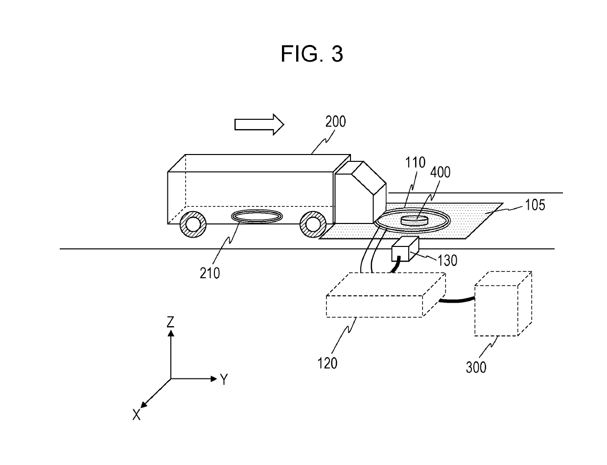
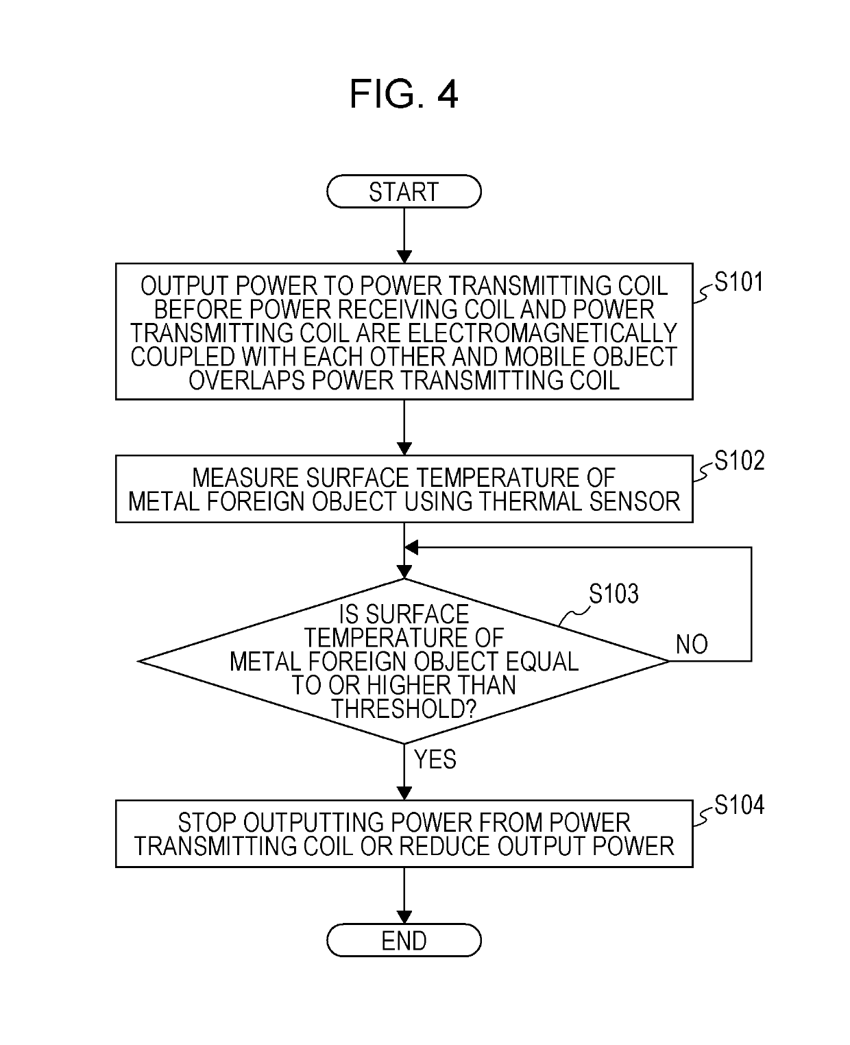
The patent describes a method to detect and remove metal objects that may come into contact with a power transmitting device. This is important because metal objects can cause damage and interrupt power transmission. The technology uses a thermal sensor that measures the surface temperature of metal objects on the power transmitting coil, and if a threshold is reached, the power transmitting coil will decrease or stop outputting power to prevent damage. The technical effect of this patent is to improve the safety and efficiency of non-contact power transmission systems by detecting and removing metal objects in a quick and effective way.

Problems solved by technology

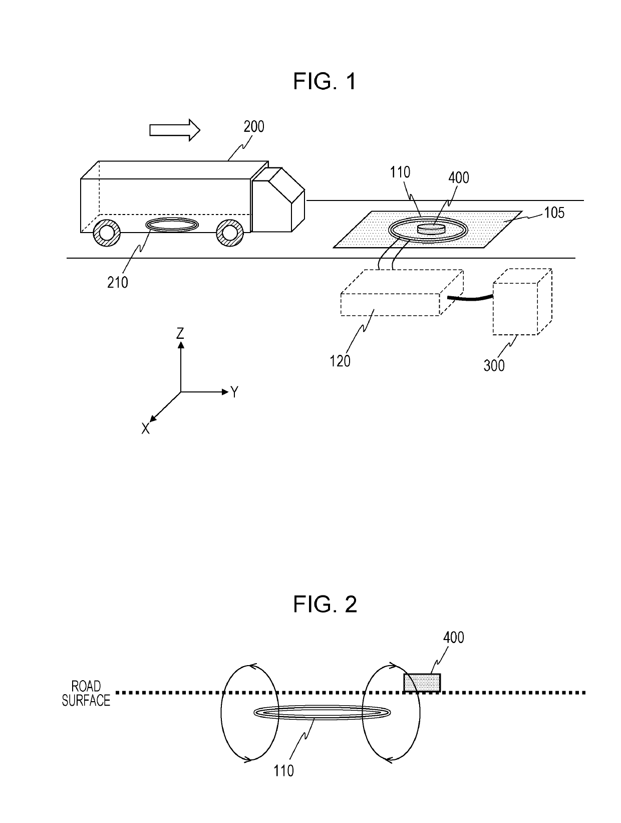
If there is a metal foreign object such as an empty can or a coin between the power transmitting coil and the power receiving coil, the surface temperature of the metal foreign object increases due to a magnetic field generated by the power transmitting coil during power transmission, which causes a safety concern.
In addition, when there is a metal foreign object between the coils, normal wireless charging might not be performed.

Method used


Image

  • Method for controlling power transmitting device, method for detecting foreign object, and power transmitting device in wireless power transmission system
  • Method for controlling power transmitting device, method for detecting foreign object, and power transmitting device in wireless power transmission system
  • Method for controlling power transmitting device, method for detecting foreign object, and power transmitting device in wireless power transmission system

Examples


first embodiment

[0100]FIG. 7 is a perspective view schematically illustrating the configuration of a wireless power transmission system according to a first exemplary embodiment of the present disclosure. The wireless power transmission system is used to supply power to an electric car, for example, on a road or in a parking lot. The wireless power transmission system includes a power transmitting device and a mobile object 200. The power transmitting device includes a power transmitting circuit 120, a power transmitting coil 110, a thermal sensor 130, and a position sensor 140. In the present embodiment, the thermal sensor 130 and the position sensor 140 are arranged above a power transmission area 105 (under a roof). The thermal sensor 130 and the power transmitting circuit 120, and the position sensor 140 and the power transmitting circuit 120, are wirelessly connected to each other. The power transmitting device can thus be an aggregation of a plurality of spatially separate components. Alterna...

second embodiment

[0134]Next, a wireless power transmission system according to a second exemplary embodiment of the present disclosure will be described. The wireless power transmission system according to the present embodiment is different from that according to the first embodiment in that if a metal foreign object is detected, a device other than a power transmitting device is notified of the presence of the metal foreign object. As a result of this operation, a person concerned can be notified of the present of the metal foreign object, and the metal foreign object can be promptly removed. The present embodiment has a large number of variations with respect to an operation performed after the other device is notified of the presence of the metal foreign object. Major variations will be described hereinafter. In each of the following examples of the present embodiment, outputting of power may be stopped or power to be output may be reduced as in the first embodiment if a metal foreign object is ...


PUM


Abstract

A method for controlling a power transmitting device includes (1) causing a power transmitting coil to output power before a power receiving coil and the power transmitting coil are electromagnetically coupled with each other and a mobile object including the power receiving coil overlaps the power transmitting coil in order for the power receiving coil and the power transmitting coil to be electromagnetically coupled with each other, (2) causing a thermal sensor to measure a surface temperature of the metal foreign object, and (3) causing, if the measured surface temperature of the metal foreign object is equal to or higher than a threshold, the power transmitting coil to reduce the power to be output or stop outputting the power.

Description

BACKGROUND1. Technical Field[0001]The present disclosure relates to a method for controlling a power transmitting device, a method for detecting a foreign object, and the power transmitting device in a wireless power transmission system.2. Description of the Related Art[0002]A wireless power transmission system used for a mobile object such as a vehicle electromagnetically couples a power transmitting coil included in a power transmitting device and a power receiving coil included in a power receiving device with each other and transmits power from the power transmitting coil to the power receiving coil. If there is a metal foreign object such as an empty can or a coin between the power transmitting coil and the power receiving coil, the surface temperature of the metal foreign object increases due to a magnetic field generated by the power transmitting coil during power transmission, which causes a safety concern. In addition, when there is a metal foreign object between the coils,...

Claims


Application Information

Patent Timeline
IPC IPC(8): B60L53/124H02J50/10H02J50/60H02J50/40H02J7/02
CPCH02J50/10B60L53/124H02J50/40H02J7/025H02J50/60B60M7/00H02J50/12H02J50/80B60L50/50Y02T10/7072Y02T10/70Y02T90/14H02J7/00H02J50/90
Inventor MATSUO, HIROYUKISAWAI, TETSURO
Owner PANASONIC INTELLECTUAL PROPERTY MANAGEMENT CO LTD
Learn More