Power conversion device

a technology of power conversion device and power supply, which is applied in the direction of electric devices, power supply testing, safety/protection circuits, etc., can solve the problem that the leakage detector disadvantageously becomes a burden on the inspection worker, and achieve the effect of reducing or preventing an increase in the work burden

Inactive Publication Date: 2022-04-07
FUJI ELECTRIC CO LTD
View PDF1 Cites 1 Cited by
  • Summary
  • Abstract
  • Description
  • Claims
  • Application Information

AI Technical Summary

Benefits of technology

[0006]The present invention has been proposed in order to solve the aforementioned problems, and an object of the present invention is to provide a power conversion device capable of significantly reducing or preventing an increase in the work burden for determining the failure of an electric leakage detector that detects electric leakage when DC power is converted into AC power and output.
[0008]As described above, the power conversion device according to this aspect of the present invention includes the failure determiner to output the pulse current to reproduce, in a simulated manner, the electric leakage that occurs in the power supply line. Furthermore, the power conversion controller is configured to determine the failure of the electric leakage detector depending on whether or not the pulse width of the pulse current as the electric leakage detection signal acquired by the electric leakage detector is within the predetermined range. Accordingly, the power conversion controller that controls power conversion of the power converter can determine whether or not the electric leakage detector that electric leakage when DC power is converted into AC power and output is operating properly. Therefore, an inspection worker can acquire the determination result of the failure of the electric leakage detector under control of the controller without performing an inspection operation on the electric leakage detector using an inspection device such as a tester. Consequently, it is possible to significantly reduce or prevent an increase in the work burden for determining the failure of the electric leakage detector that detects electric leakage when DC power is converted into AC power and output.
[0009]Furthermore, the power conversion controller is configured to stop the power conversion operation of the power converter based on the detection result of the electric leakage detector. Accordingly, when the electric leakage detector acquires the detection result indicating that electric leakage has occurred in the power supply line, the output of the AC power from the power converter can be stopped. In general, as compared with a case in which conduction in the power supply line is cut off by a mechanical breaking device such as a breaker, conduction in the power supply line can be more quickly cut off by stopping the power conversion operation of the power converter under control of the power conversion controller. Therefore, conduction in the power supply line can be quickly cut off by performing a control to stop the power conversion operation of the power converter instead of using a mechanical breaking device such as a breaker. Consequently, when electric leakage is detected when DC power is converted into AC power and output, conduction of the AC power can be cut off more quickly.
[0010]In the aforementioned power conversion device according to this aspect, the power conversion controller is preferably configured to acquire a determination result that the electric leakage detector is normal when the pulse width of the pulse current as the electric leakage detection signal acquired by the electric leakage detector is within the predetermined range, acquire a determination result that a layer short has occurred in the electric leakage detector when the pulse width of the pulse current as the electric leakage detection signal acquired by the electric leakage detector is a value larger than the predetermined range, and acquire a determination result that the electric leakage detector has been disconnected when the pulse width of the pulse current as the electric leakage detection signal acquired by the electric leakage detector is a value smaller than the predetermined range. Accordingly, the inspection worker can recognize the more detailed state of the electric leakage detector from the determination result based on the pulse current output by the failure determiner. Therefore, when the electric leakage detector is inspected, the inspection worker can easily recognize the detailed state of the electric leakage detector by referring to the automatically acquired determination result.

Problems solved by technology

However, an inspection operation to determine the failure of the electric leakage detector disadvantageously becomes a burden on an inspection worker.

Method used


Image

  • Power conversion device
  • Power conversion device
  • Power conversion device

Examples


modified examples

[0060]The embodiment disclosed this time must be considered as illustrative in all points and not restrictive. The scope of the present invention is not shown by the above description of the embodiment but by the scope of claims for patent, and all modifications (modified examples) within the meaning and scope equivalent to the scope of claims for patent are further included.

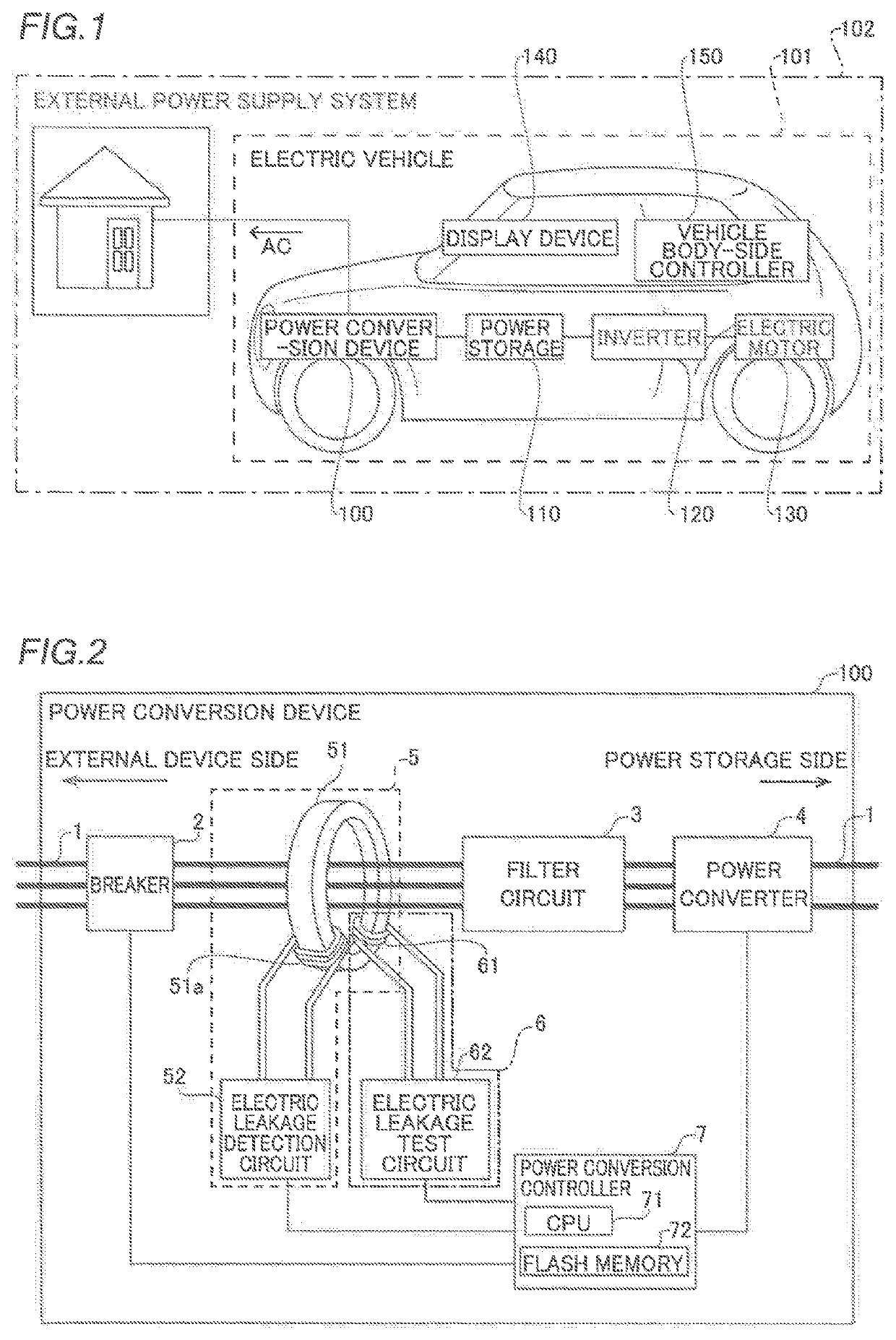
[0061]For example, while the power converter is mounted on the electric vehicle (vehicle) in the aforementioned embodiment, the present invention is not limited to this. For example, the power converter may not be mounted on the vehicle. That is, the power converter may be mounted on a marine vessel, for example. Alternatively, the power converter may be mounted on a power conversion device that is configured independently of and separately from the vehicle.

[0062]While the power converter converts the DC power output from the power storage mounted on the electric vehicle (vehicle) into AC power in the aforementi...


PUM


Abstract

A power conversion device includes an electric leakage detector, a failure determiner to output a pulse current to reproduce, in a simulated manner, electric leakage, and a power conversion controller configured to control power conversion. The power conversion controller is configured to determine a failure of the electric leakage detector depending on whether or not a pulse width of a pulse current as an electric leakage detection signal acquired by the electric leakage detector is within a predetermined range.

Description

CROSS-REFERENCE TO RELATED APPLICATION[0001]The present application claims priority of Japanese Patent Application No. 2020-166765 filed Oct. 1, 2020, the disclosure of which is hereby incorporated by reference.BACKGROUND OF THE INVENTIONField of the Invention[0002]The present invention relates to a power conversion device, and more particularly, it relates to a power conversion device that detects electric leakage.Description of the Background Art[0003]A power conversion device that detects electric leakage is known in general, as disclosed in Japanese Patent Laid-Open No. 2011-135663, for example.[0004]An in-vehicle charging system (power conversion device) described in Japanese Patent Laid-Open No. 2011-135663 includes a power conversion circuit (power converter) that converts commercial power supplied via a power supply line and supplies charging power to a high-voltage battery mounted on a vehicle. This in-vehicle charging system further includes a breaking means (breaker) that...

Claims


Application Information

Patent Timeline
Patent Type & Authority Applications(United States)
IPC IPC(8): H02M7/797H02M1/36B60L53/60G01R31/52
CPCH02M7/797H02M1/36B60L2210/40G01R31/52B60L2210/30B60L53/60G01R31/42B60L55/00B60L3/0069H02H3/335H02M7/219H02M1/32H02M1/0009H02J7/00304Y02E60/00Y02T10/70Y02T10/72Y02T10/7072Y02T90/12Y04S10/126
Inventor ANDO, NOBUHISAKATSUMATA, HIROKI
Owner FUJI ELECTRIC CO LTD
Why Eureka
Try Eureka