Short-circuit protective circuit

a protective circuit and short circuit technology, applied in the direction of electric variable regulation, process and machine control, instruments, etc., can solve the problems of inability to meet the requirements of short circuit protection circuit, increase in cost, and regulator breakage, and achieve the effect of simple circuit configuration

Inactive Publication Date: 2005-06-30
ORION ELECTRIC CO LTD
View PDF2 Cites 0 Cited by
  • Summary
  • Abstract
  • Description
  • Claims
  • Application Information

AI Technical Summary

Benefits of technology

[0005] It is an object of the invention to provide a short-circuit protective circuit of a constant-voltage power-supply circuit capable of realizing a short-circuit protection with a simple circuit configuration in a power-supply circuit provided with a plurality of power-supply lines.
[0006] The short-circuit protective circuit comprises a regulator having an input terminal connected to a specific power-supply line of a plurality of power-supply lines, an output terminal for outputting a constant voltage and an output control terminal, a plurality of constant-voltage circuits connected to each power-supply line other than the specific power-supply line, each constant-voltage circuit allowing voltages of each power-supply line to be constant based on the constant voltage supplied from the output terminal of the regulator, a voltage detection circuit connected to each power-supply line other than the specific power-supply line for detecting a voltage drop at an output side thereof and outputting a detection signal, and an operation circuit connected to the output control terminal of the regulator for stopping the output voltage from the regulator in response to the detection signal outputted from the voltage detection circuit.
[0007] With the circuit configuration set forth above, if there occurs a voltage drop at any of the plurality of power-supply lines, output voltages of all the power-supply lines are stopped, thereby realizing the short-circuit protective circuit which is safer relative to a short circuit.
[0008] That is, since the regulator is provided on the specific power-supply line and constant voltage circuits are provided on the other power-supply lines for allowing voltages of the other power-supply lines to be constant voltages based on constant voltages outputted from the regulator, if the output of the regulator is stopped, all the power-supply lines are stopped in output thereof at once. Accordingly, the constant voltage circuits in each power-supply line have a function to implement ON / OFF control relative to the voltage of each power-supply line.
[0009] Further, if the voltage detection circuit provided on each power-supply line detects a voltage drop at the output side of the constant voltage circuits, thereby detecting the voltage drop at either power-supply line, the operation circuit sends out a signal to the output control terminal of the regulator to stop the output of the regulator. As a result, if there occurs a voltage drop at any of the power-supply lines owing to short-circuit, the operation circuits operates to stop the output of the regulator.

Problems solved by technology

As for a constant-voltage power-supply circuit, a voltage of a power-supply line is controlled to a constant voltage by connecting a regulator to the power-supply line, wherein if a load circuit is short-circuited at an output side of the regulator owing to some cause, there occurs a voltage drop, so that a large current flows to the regulator, causing a problem of the breakage of the regulator owing to overheat of the regulator.
However, if such a circuit configuration is used for a power-supply circuit provided with a plurality of power-supply lines, the regulator has to be disposed for each power-supply line, so that the increase of cost is inevitable.
Further, even if one power-supply line is short-circuited to stop the supply of power, the remaining power-supply lines continue to supply power so that there is a possibility the short-circuited load circuit influences upon load circuits connected to the remaining power-supply lines, and if the supply of power continues, wasteful power consumption is required.

Method used


Image

  • Short-circuit protective circuit
  • Short-circuit protective circuit

Examples


Embodiment Construction

[0012] An embodiment of the invention is now described in detail. Since the working example described hereinafter is a preferred concrete example for working out the invention, it is variously limited technically, but the invention is not limited to the working example unless explicitly limiting the invention to the working example.

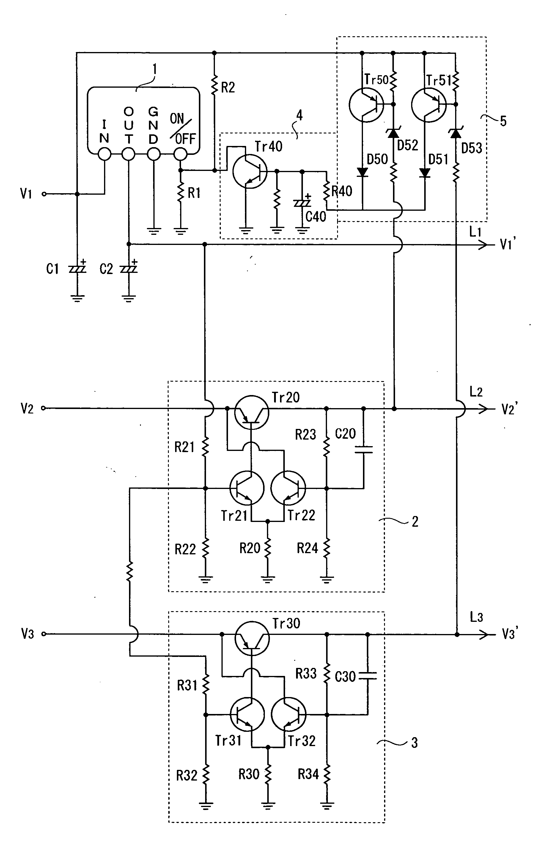
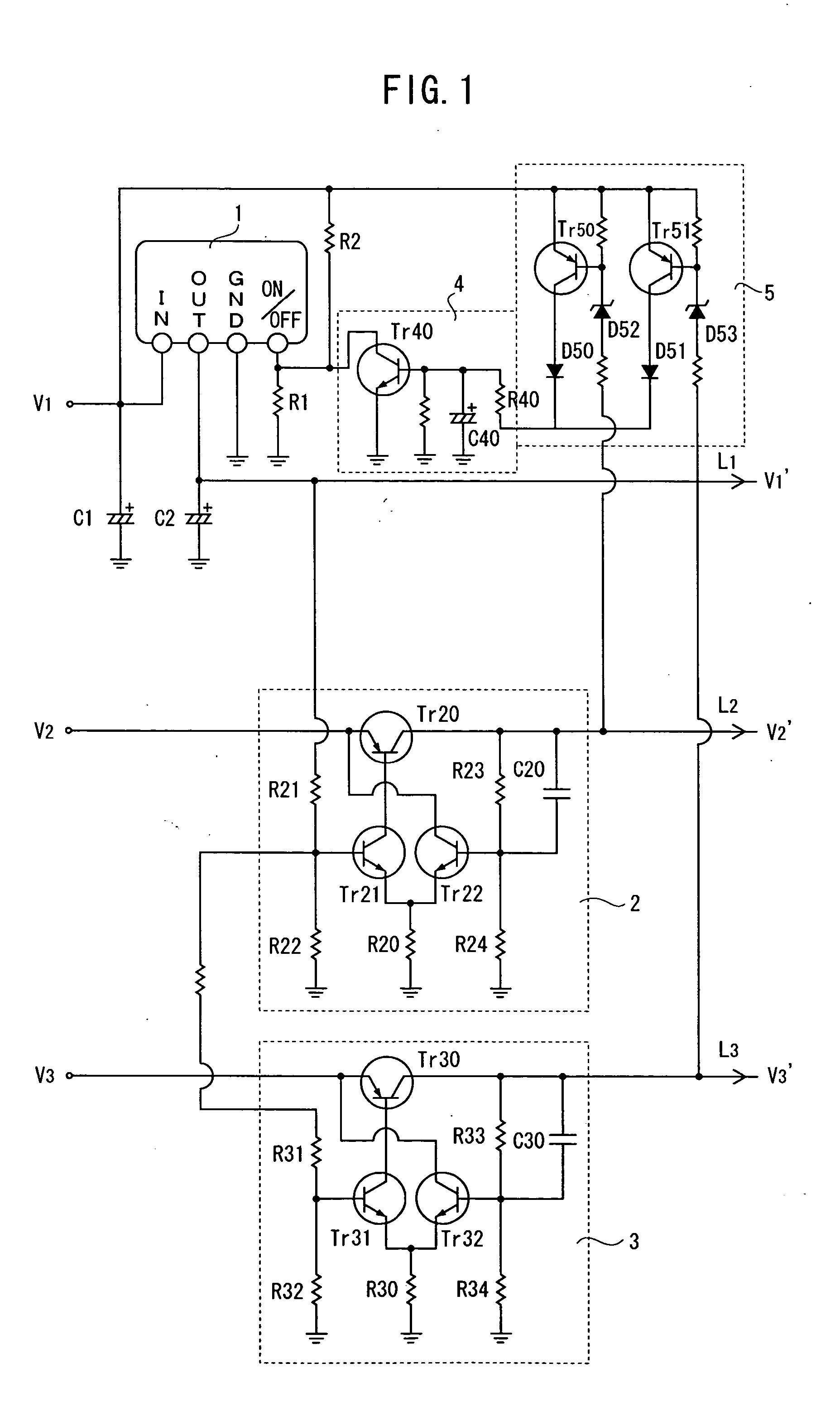
[0013]FIG. 1 is a circuit configuration relating to the embodiment of the invention. In FIG. 1, voltages V1 to V2 are supplied from a power-supply circuit, not shown, through power-supply lines.

[0014] The power-supply line through which the voltage V1 (hereinafter referred to as power-supply line of the voltage V1) is supplied is connected to an input terminal IN of a regulator 1. The regulator 1 has an output terminal OUT for outputting a predetermined constant voltage, a ground terminal GND to be grounded and an output control terminal ON / OFF for turning on or off the output of the regulator 1 in addition to the input terminal IN, wherein the input an...


PUM


Abstract

It is an object of the invention to provide a short-circuit protective circuit of a constant-voltage power-supply circuit capable of realizing a short-circuit protection with a simple circuit configuration in a power-supply circuit provided with a plurality of power-supply lines. A regulator is connected to one of a plurality of power-supply lines, and a constant voltage is outputted from an output terminal of the regulator to one output line. An output voltage from the regulator is inputted to constant-voltage circuits as a reference voltage and other output constant voltages are supplied to other output lines. A voltage detection circuit is connected to the other output lines, wherein if there occurs a voltage drop in either output line, a detection signal is outputted to an operation circuit, thereby turning off an output control terminal of the regulator. Accordingly, an output of the regulator is stopped so that the output lines are stopped all at once.

Description

FIELD OF THE INVENTION [0001] The invention relates to a short-circuit protective circuit of a constant-voltage power-supply circuit provided with a plurality of power-supply lines. BACKGROUND OF THE INVENTION [0002] As for a constant-voltage power-supply circuit, a voltage of a power-supply line is controlled to a constant voltage by connecting a regulator to the power-supply line, wherein if a load circuit is short-circuited at an output side of the regulator owing to some cause, there occurs a voltage drop, so that a large current flows to the regulator, causing a problem of the breakage of the regulator owing to overheat of the regulator. [0003] To cope with such a problem, a short-circuit protective circuit is provided in the constant-voltage power-supply circuit. For example, JP 5-252649A discloses that potential detection means for detecting the difference between an input voltage and an output voltage of a regulator exceeds a prescribed voltage wherein an output of the regul...

Claims


Application Information

Patent Timeline
Patent Type & Authority Applications(United States)
IPC IPC(8): G05F1/00G05F1/10G05F1/565H02H7/00
CPCG05F1/565
Inventor TANI, KATSUHIKO
Owner ORION ELECTRIC CO LTD
Why Eureka
Try Eureka