
Driving circuit, driving method, and display device

Inactive Publication Date: 2021-08-19
TCL CHINA STAR OPTOELECTRONICS TECH CO LTD
View PDF0 Cites 0 Cited by
  • Summary
  • Abstract
  • Description
  • Claims
  • Application Information

AI Technical Summary

Benefits of technology

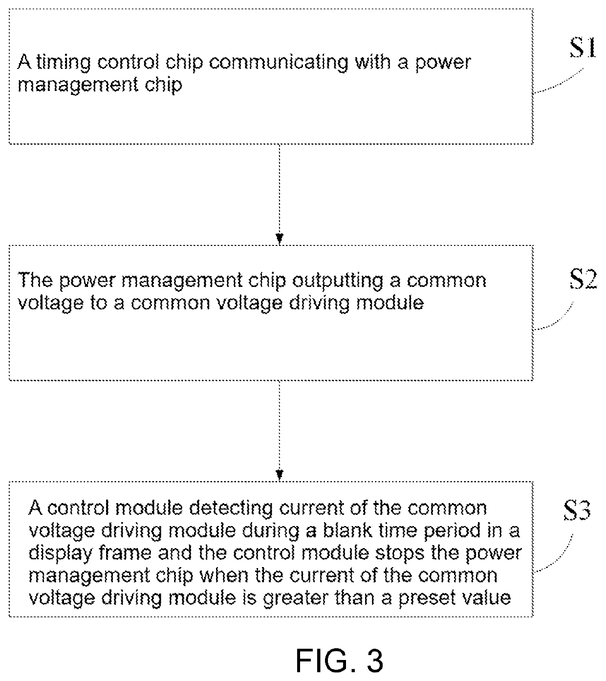
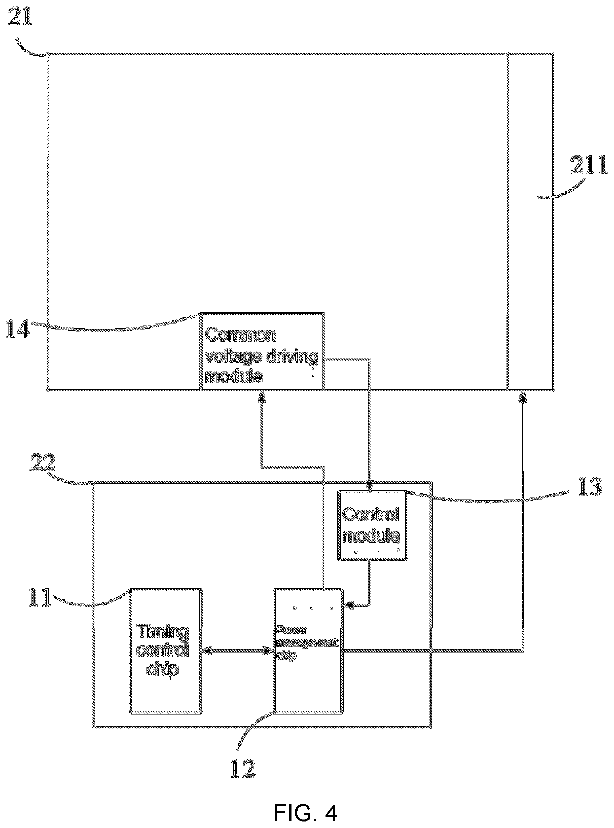
The patent application provides a driving circuit for a display panel that includes a power management chip and control module. The control module detects the current of the common voltage driving module during a blank time period in a display frame and controls the power management chip to stop outputting the common voltage when the current value exceeds a predetermined level. This prevents a melting screen from damaging the display screen due to high current levels and solves the technical problem of a current driving circuit causing damage to the display screen.

Problems solved by technology

However, during a signal transmission process, due to particles and other foreign objects appearing in the display screen, between clock signal lines or between the clock signal lines and common voltage lines are short-circuited, resulting in a large current on the common voltage lines, causing temperature in a display panel to rise, causing the display screen to melt and causing damage to the display screen.
Therefore, an existing driving circuit has the technical problem that current on the common voltage line is relatively large and the display screen is damaged.

Method used


Image

  • Driving circuit, driving method, and display device
  • Driving circuit, driving method, and display device
  • Driving circuit, driving method, and display device

Examples


Embodiment Construction

[0031]The present application provides a driving circuit, a driving method, and a display device. In order to make the purpose, technical solution, and effect of the present application clearer and more definite, the present application is further described in detail below with reference to the accompanying drawings and examples. It is understood that the specific embodiments described herein are only used to explain the present application and are not used to limit the present application.

[0032]In view of the technical problem that a current driving circuit has a large current on a common voltage line and damages a display screen, embodiments of the present application are used to solve the issues.

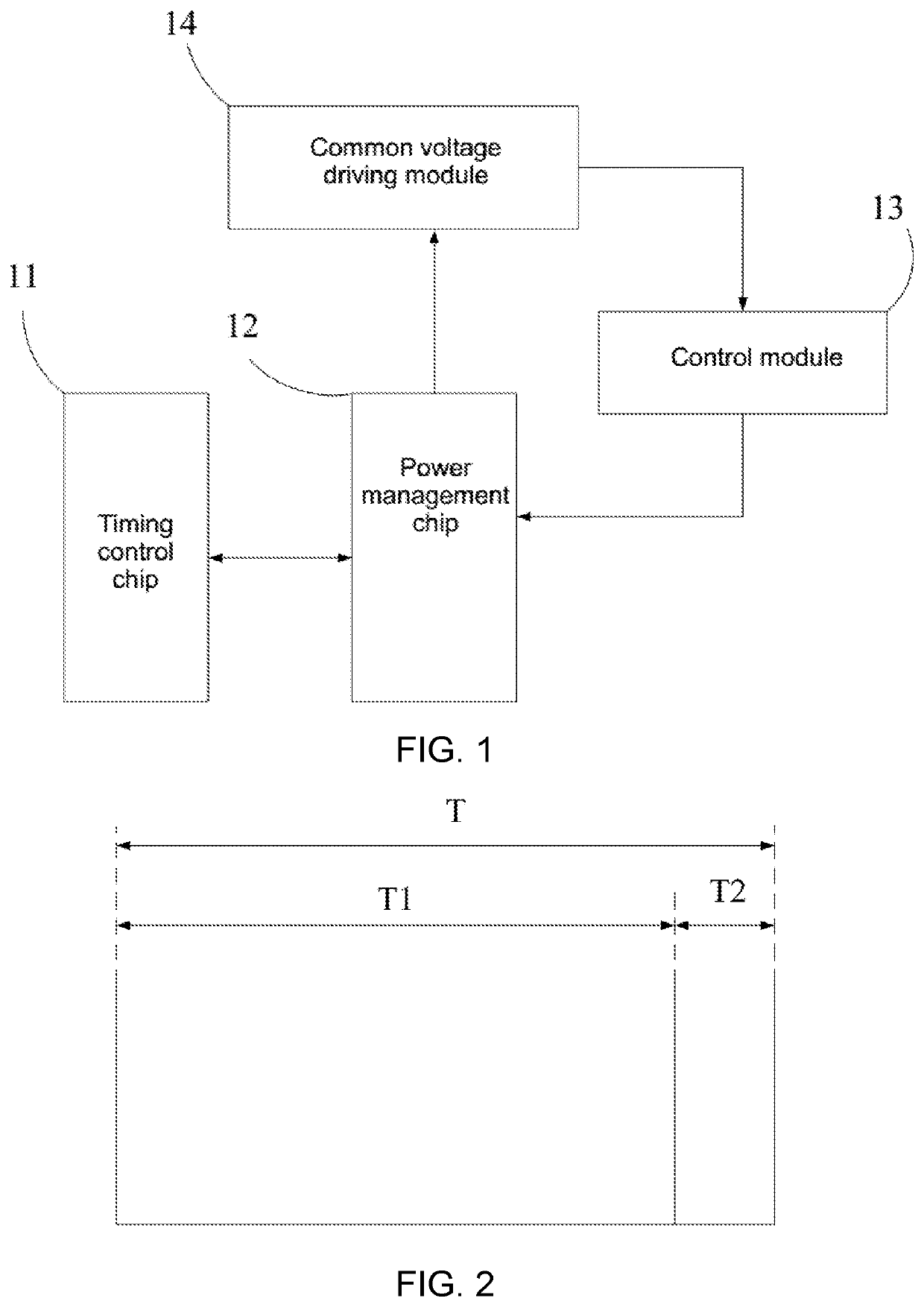
[0033]As shown in FIG. 1, an embodiment of the present application provides a driving circuit. The driving circuit includes:

[0034]A power management chip 12 configured to output a common voltage to a common voltage driving module 14.

[0035]A control module 13 configured to detect a current...


PUM


Abstract

A driving circuit, a driving method, and a display device are provided. The driving circuit is applied to a display panel. The driving circuit sets a control module, so that when a current value of the control module on a common voltage driving module is greater than a preset value, a power management chip is controlled to stop outputting a common voltage, so that when a current on a common voltage line is large, an output voltage to the common voltage driving module is stopped, thereby avoiding a phenomenon that a melting screen damages a display screen due to large current.

Description

FIELD OF INVENTION[0001]The present disclosure relates to the field of display technologies, and more particularly to a driving circuit, a driving method, and a display device.BACKGROUND OF INVENTION[0002]In a driving circuit of an existing display screen, a power control chip and a level conversion circuit are used to transmit voltage signal, and each channel of the level conversion circuit is detected. When a large current occurs, the level conversion circuit is turned off for overcurrent protection of high and low potential voltages. However, during a signal transmission process, due to particles and other foreign objects appearing in the display screen, between clock signal lines or between the clock signal lines and common voltage lines are short-circuited, resulting in a large current on the common voltage lines, causing temperature in a display panel to rise, causing the display screen to melt and causing damage to the display screen.[0003]Therefore, an existing driving circu...

Claims


Application Information

Patent Timeline
IPC IPC(8): G09G3/20
CPCG09G3/20G09G2310/08G09G2310/0286G09G2330/021G09G3/3655G09G3/3696G09G2330/025G09G2330/028G09G2330/045G09G2330/12
Inventor LI, WENFANGCAO, DAN
Owner TCL CHINA STAR OPTOELECTRONICS TECH CO LTD
Learn More