
Circuit Body for Vehicle

a technology for circuit bodies and vehicles, applied in the direction of electric/fluid circuits, vehicle components, electrical apparatus, etc., can solve the problems of increasing the size of the circuit body itself, increasing the number of electric wires that make up the circuit body, and increasing the weight of the circuit body. , the steps of manufacturing the circuit body also tend to be complicated, and the effect of increasing the weigh

Active Publication Date: 2019-09-12
YAZAKI CORP
View PDF0 Cites 0 Cited by
  • Summary
  • Abstract
  • Description
  • Claims
  • Application Information

AI Technical Summary

Benefits of technology

The invention aims to simplify the structure of a circuit body for a vehicle while keeping its function required. The circuit body is built by trunk harnesses and branch harnesses, while supply of electric power and transmission of communication signals to the electric components are achieved by control boxes distributed on the circuit body. By using multiplex communication and grounding routes separately for the power circuit and signal circuit, noise from a large current flow can be reduced, ensuring reliable operation of the electric components. Overall, the invention allows for more efficient and cost-effective manufacturing of circuit bodies for vehicles.

Problems solved by technology

Recently with increase of electric components mounted on vehicles and complication of control thereof, structures of circuit bodies (wire harnesses) tend to be complicated.
As a result, the number of electric wires constituting each circuit body tends to increase, and the circuit body itself tends to increase in size.
Thus, the circuit body tends to increase in weight.
In addition, with increase in different kinds of vehicles to be mounted with circuit bodies or increase in kinds of optional electric components, the number of kinds of circuit bodies to be manufactured tends to increase, and steps of manufacturing the circuit bodies also tend to be complicated.
Thus, the manufacturing cost and the manufacturing time of each circuit body tend to increase.

Method used


Image

  • Circuit Body for Vehicle
  • Circuit Body for Vehicle
  • Circuit Body for Vehicle

Examples


embodiment

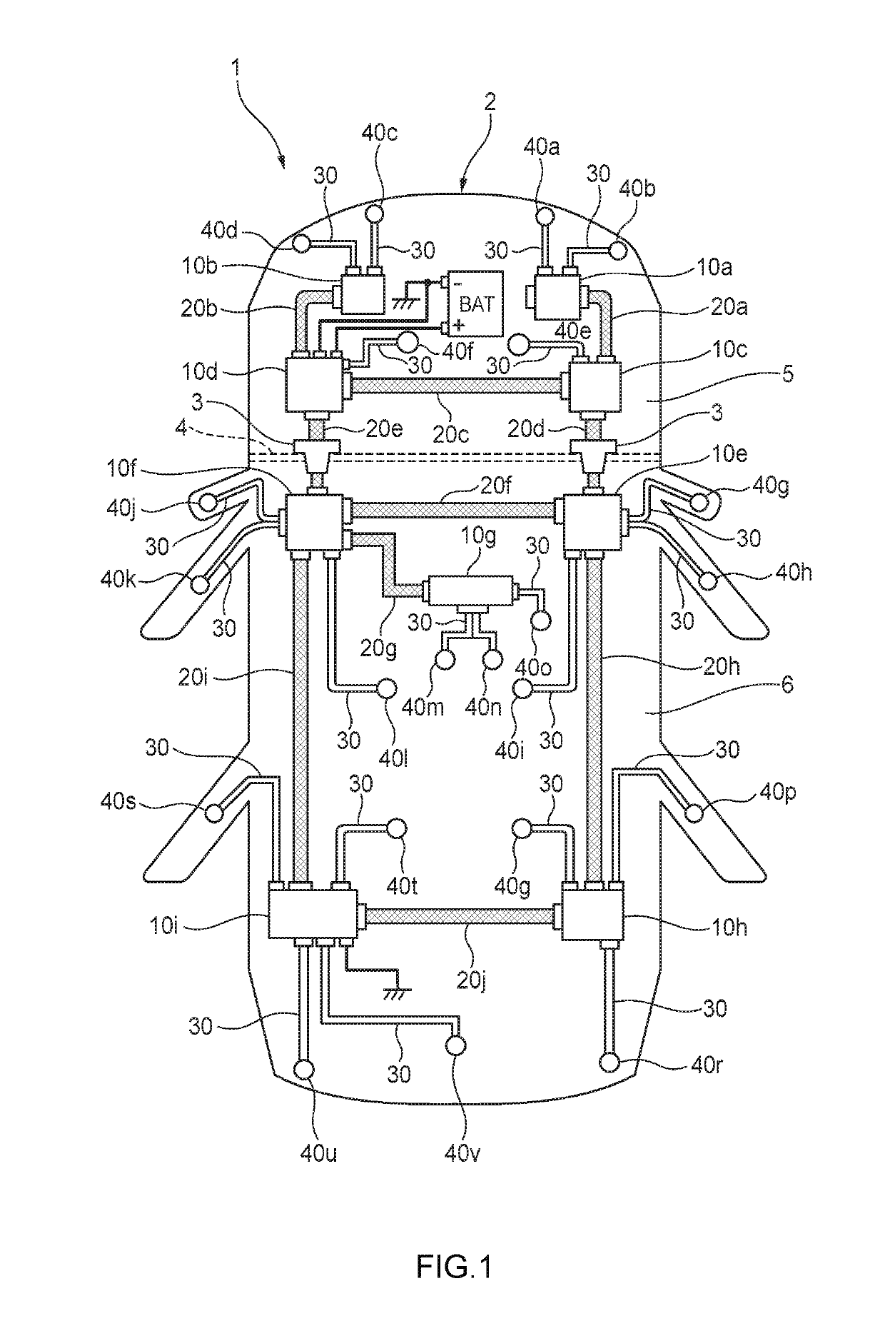
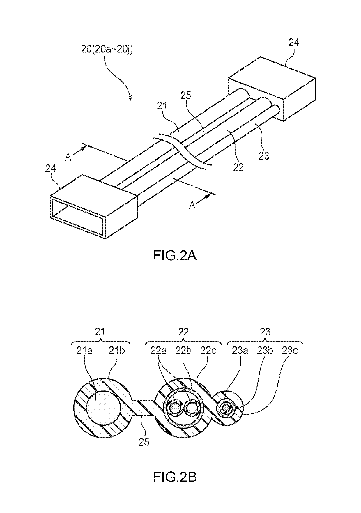
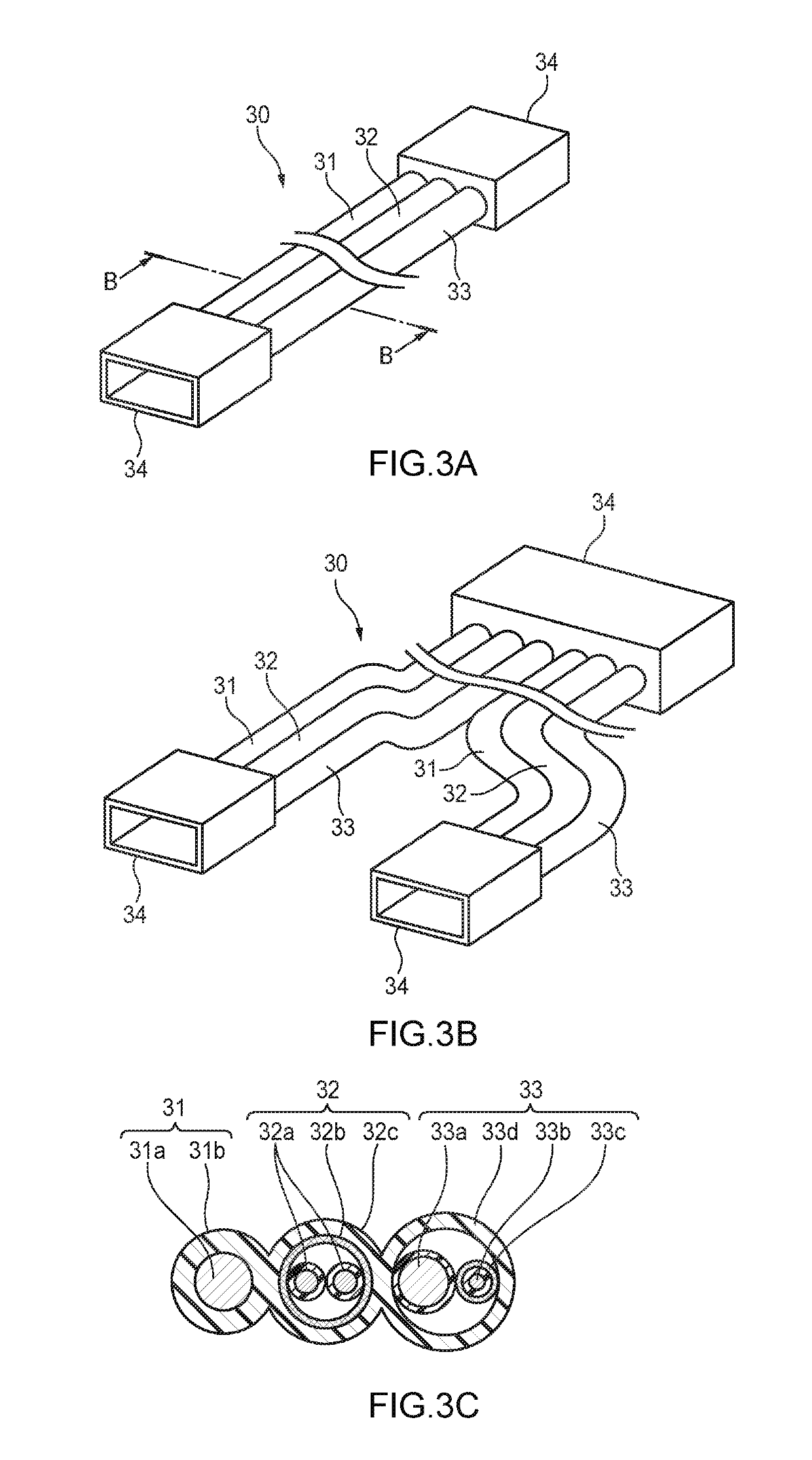
[0033]A circuit body (wire harness 1) for a vehicle according to an embodiment of the invention will be described below with reference to FIG. 1, FIGS. 2A and 2B, FIGS. 3A to 3C, and FIG. 4.

[0034]As shown in FIG. 1, the wire harness 1 according to the embodiment of the invention is in use routed on a vehicle body 2 mounted with various electric components 40 (40a to 40v). The wire harness 1 has a plurality of electric connection boxes 10 (10a to 10i), trunk harnesses 20 (20a to 20i) each electrically connecting one electric connection box 10 to another electric connection box 10 adjacent thereto, and branch harnesses 30 each electrically connecting one electric connection box 10 to one electric component 40 adjacent thereto.

[0035]Each electric connection box 10 has a plurality of connector reception holes (not shown). A connector 24 (see FIG. 2A and 2B) of at least one trunk harness 20 and a connector 34 (see FIGS. 3A-3C) of at least one branch harness 30 are connected to the connec...


PUM


Abstract

A circuit body (1) for a vehicle includes: a plurality of control boxes (10) dispersedly arranged on the circuit body; a trunk harness (20) connecting one of the control boxes to another of the control boxes; and a branch harness (30) connecting the control box the electric component. The control boxes, the trunk harness and the branch harness is configured to ground a power circuit and a signal circuit through grounding routes different from each other. The power circuit supplies the electric power from a power source (BAT) to the electric component through the control boxes. The signal circuit transmits a communication signal between the control boxes and the electric component and between one of the control boxes and another of the control boxes.

Description

CROSS-REFERENCES TO RELATED APPLICATION(S)[0001]This application is based on and claims priority from Japanese Patent Application No. 2018-041026 filed on Mar. 7, 2018, and the entire contents of which are incorporated herein by reference.BACKGROUNDField of the Invention[0002]The present invention relates to a circuit body for a vehicle.Description of Related Art[0003]A circuit body (so-called wire harness) for connecting power sources or the like mounted on a vehicle with various electric components or the like has been known. Such a circuit body is generally arranged so that electric power can be properly supplied from an alternator (generator) and a battery as main power sources to a large number of electric components (such as an ECU and various accessories), a mode can be properly changed over between a power feeding mode and a power blocking mode, and various communication signals can be transmitted.[0004]Specifically such a circuit body (wire harness) is typically constituted...

Claims


Application Information

Patent Timeline
Patent Type & Authority Applications(United States)
IPC IPC(8): B60R16/03B60R16/02B60R16/023H02H7/22
CPCB60R16/03H02H7/226B60R16/0207B60R16/0238H02G3/16B60R16/0215B60R16/0315H02B1/26
Inventor NAKAMURA, MASASHIFURUKAWA, MASAHIROENOMOTO, SATOSHIKANAZAWA, AKIYOSHI
Owner YAZAKI CORP
Learn More