Fan

a fan and fan body technology, applied in the field of fans, can solve the problems of time-consuming assembly, labor-intensive fan assembly, inconvenient assembly, etc., and achieve the effects of reducing vibration, improving fan utility, and increasing air volum

Inactive Publication Date: 2019-09-12
SUNONWEALTH ELECTRIC MACHINE IND
View PDF13 Cites 1 Cited by
  • Summary
  • Abstract
  • Description
  • Claims
  • Application Information

AI Technical Summary

Benefits of technology

[0018]In the example, the fan further includes a buffering member. One of the two frames includes a receiving portion, another of the two frames includes another receiving portion, and the receiving portion and the other receiving portion are connected to each other to receive the buffering member. Thus, the buffering member can reduce the vibration.
[0019]In the example, the fan further includes another impeller a

Problems solved by technology

Thus, during the assembly of the fan, it requires labor effort to align the screw holes of the components and to respectively insert the fasteners through the pairs of the screw holes.
Disadvantageou

Method used


Image

  • Fan
  • Fan
  • Fan

Examples


Embodiment Construction

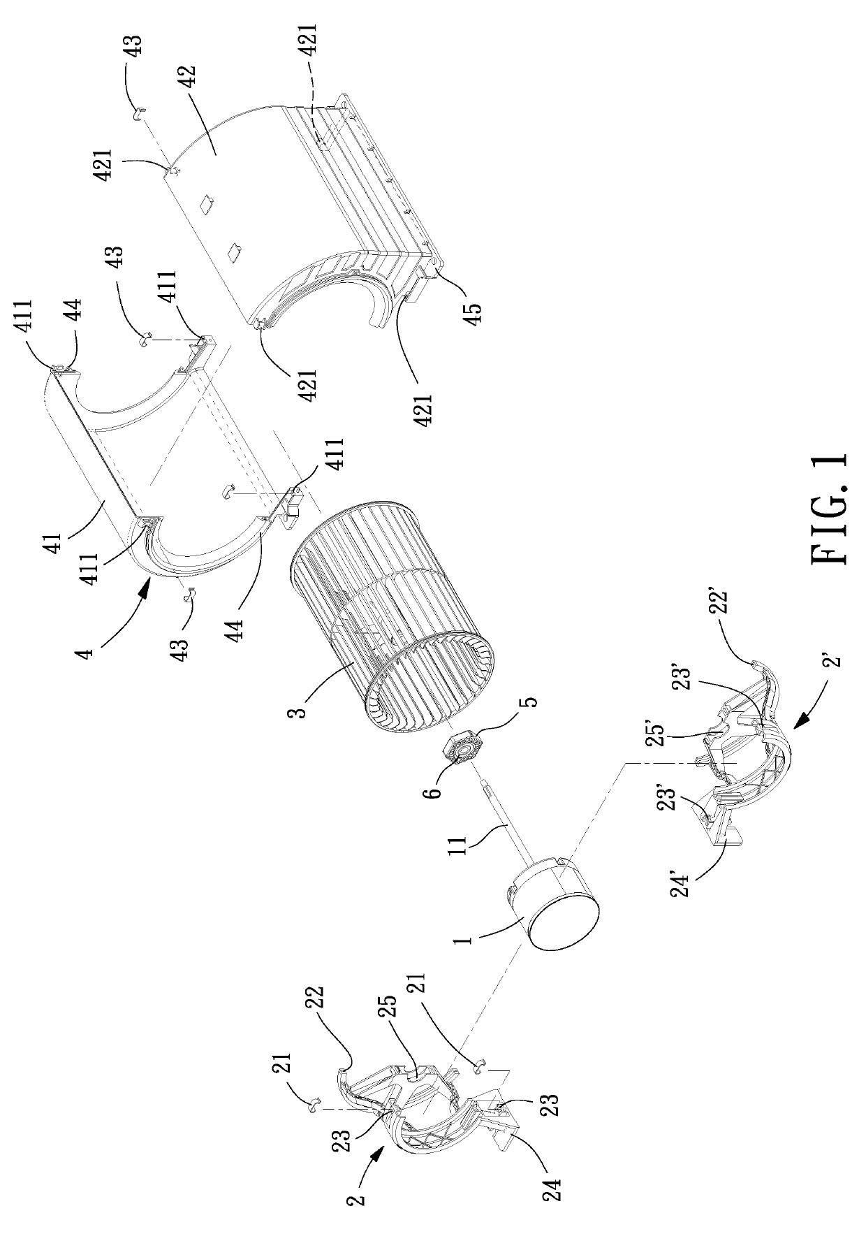
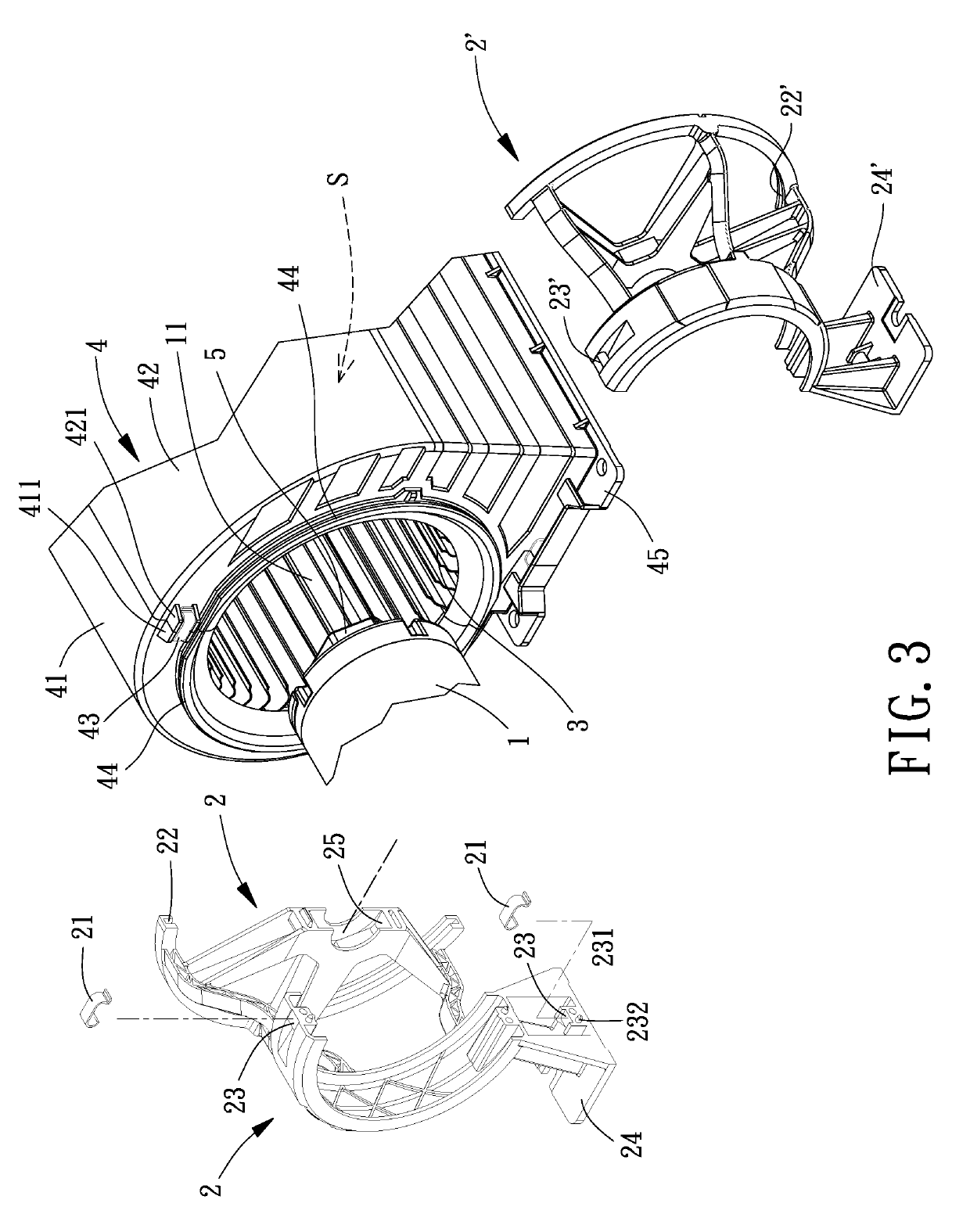
[0029]FIG. 1 shows a fan according to a first embodiment of the invention which can be installed in an air-curtain apparatus. The fan includes a motor 1, two frames 2 and 2′ coupled with the outer periphery of the motor 1, an impeller 3 connected to the motor 1, and a housing assembly 4 housing the impeller 3.

[0030]The motor 1 provides power to the impeller 3. The motor 1 includes a shaft 11 rotatably connected to the impeller 3. In this embodiment, the motor 1 can have any structure and shape as long as the motor 1 can smoothly drive the impeller 3 to rotate.

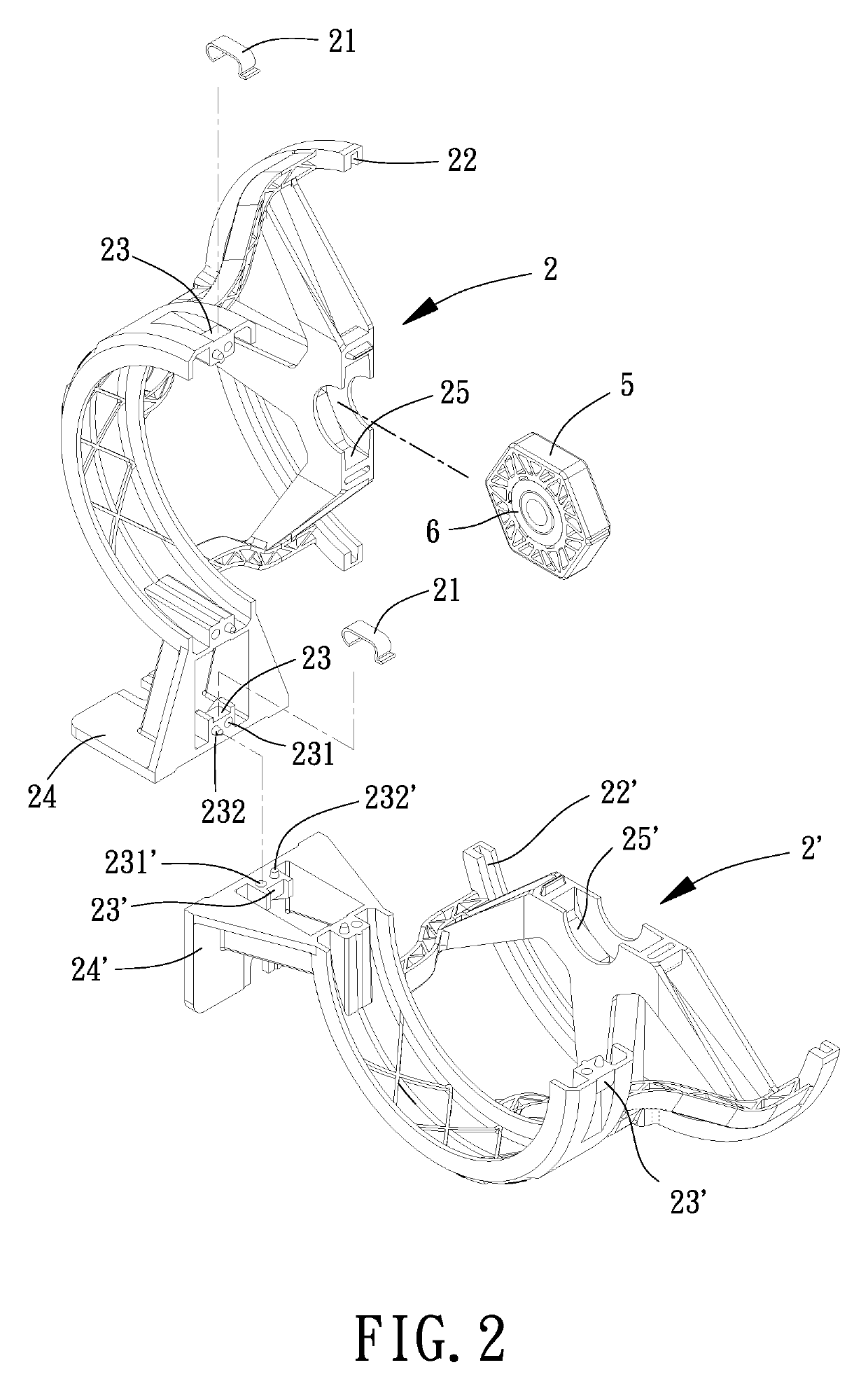
[0031]Referring to FIG. 2, the two frames 2 and 2′ are coupled with the outer periphery of the motor 1 by way of fastening, which is done preferably with a plurality of fastening members 21. Each of the frames 2 and 2′ includes at least one groove 22, 22′. One of the frames 2 and 2′ includes at least one first engagement portion 23. Another of the frames 2 and 2′ includes at least one second engagement portion 23′. The at least...


PUM


Abstract

A fan includes a motor, two frames, an impeller and a housing assembly. The two frames are coupled with an outer periphery of the motor and are engaged with each other by way of fastening. Each of the two frames includes one groove. The impeller is connected to the motor and is driven to rotate by the motor. The housing assembly houses the impeller and includes first and second housing parts. The first and second housing parts are engaged with each other by way of fastening. A protruding lip is provided on one of two end faces of the first housing part which is relatively adjacent to the motor. Another protruding lip is provided on one of two end faces of the second housing part which is relatively adjacent to the motor. The protruding lip and the other protruding lip are engaged with the grooves of the two frames.

Description

CROSS REFERENCE TO RELATED APPLICATION[0001]The application claims the benefit of Taiwan application serial No. 107107922, filed on Mar. 8, 2018, and the entire contents of which are incorporated herein by reference.BACKGROUND OF THE INVENTION1. Field of the Invention[0002]The present invention generally relates to a fan and, more particularly, to a fan which can improve the convenience in assembly.2. Description of the Related Art[0003]An air-curtain apparatus with a fan is generally installed in the head of the door frame at both the entrance and the exit of a supermarket or a department store in order to prevent the escaping of the cool air and the intrusion of the foreign objects, such as mosquitos, flies and / or the insects. The air blows downwardly to create an air wall between the indoor space and the outdoor space, which prevents the escaping of the cool air and the entry of the polluted air or dust.[0004]The fan as mentioned above includes a motor frame, an impeller assembly...

Claims


Application Information

Patent Timeline
IPC IPC(8): F04D29/62F04D17/08F04D29/42F24F9/00
CPCF04D29/624F04D29/4226F24F9/00F04D17/08F04D25/163F04D29/626F04D29/002F04D25/08H02K7/14H02K7/003H02K5/24H02K5/00F04D17/162F04D25/0606F04D25/06F04D29/424
Inventor HORNG, ALEXHU, WAN-LINGWANG, YI-HAO
Owner SUNONWEALTH ELECTRIC MACHINE IND
Why Eureka
Try Eureka