
Optical vital signs sensor

a vital signs sensor and optical technology, applied in the field of optical vital signs sensors, can solve the problem that the output of the photo detector cannot be used to detect vital signs of users, and achieve the effect of improving the detection or estimation of vital signs of users

Pending Publication Date: 2019-09-19
KONINKLJIJKE PHILIPS NV
View PDF0 Cites 6 Cited by
  • Summary
  • Abstract
  • Description
  • Claims
  • Application Information

AI Technical Summary

Benefits of technology

This invention aims to improve the detection and estimation of vital signs of a user. It uses an optical device to measure these signs and calibrates the information based on a blood pressure measurement from an external device. This calibration helps increase the accuracy of the blood pressure measurement. Overall, this invention allows for more precise monitoring of a user's vital signs.

Problems solved by technology

If the PPG sensor is, however, not anymore in direct contact with the skin of the user, e.g. if a loss of skin contact has occurred, the output of the photo detector cannot be used to detect vital signs of a user.

Method used


Image

  • Optical vital signs sensor
  • Optical vital signs sensor
  • Optical vital signs sensor

Examples


first embodiment

[0054]Preferably, the user should keep his wrist and the wrist worn device at the level of his heart during the measurement period. The blood pressure estimation procedure may be initiated by the user for example by pressing a button. the compression unit 150, 160 is activated in order to apply pressure on the PPG sensor 102 thereby pressing the PPG sensor into the skin of the user. The PPG sensor 102 will then detect blood volume variations of the blood in the skin arterioles. The force applied to the skin of the user can linearly increase from 0 N to a predefined maximum value.

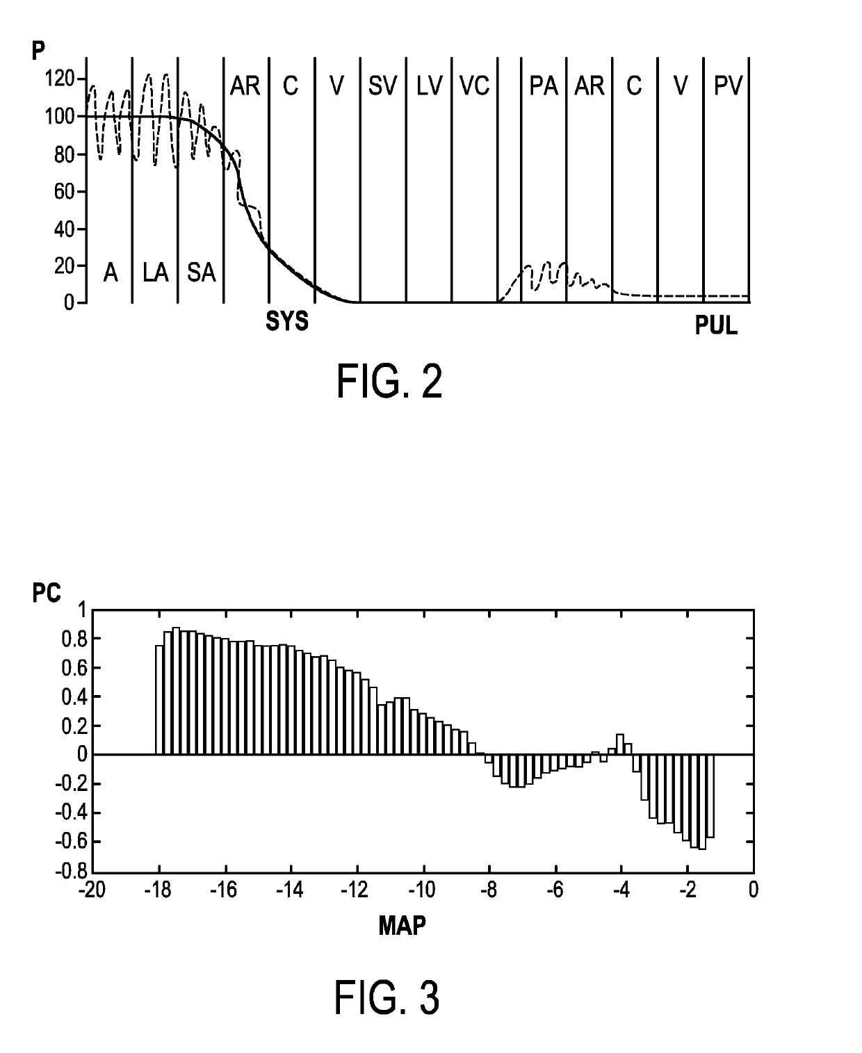
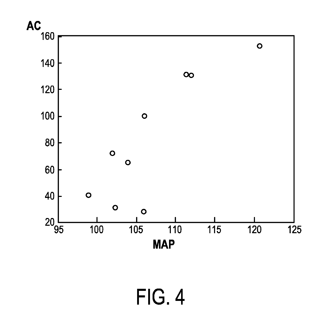
[0055]The output of the PPG sensor 102 as well as the output of the force transducer 130 are forwarded to the processing unit 140. The processing unit 140 may comprise a unit for assessing the quality of the output of the sensor. The processing unit 140 may furthermore comprise an extraction unit for deriving real time features from the PPG output signal. These features may include the pulsatile AC componen...

second embodiment

[0059] the user must apply the force to press the PPG sensor 100 against the skin of the user himself.

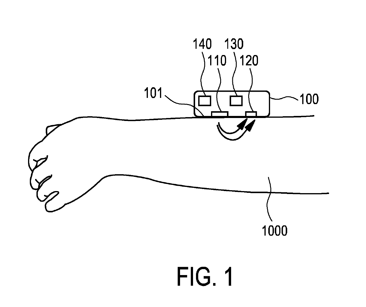
[0060]FIG. 8 shows a schematic representation of a wrist 1002 of a user together with the optical vital signs sensor during a measurement according to the second embodiment. Here, the user must apply the required force to press the PPG sensor 102 against the skin 1000 by pressing the optical vital signs sensor against his skin. The amount of pressure applied is detected by the force transducer 130. When the PPG sensor 102 is pressed against the skin of the user, the PPG sensor 102 can be activated to detect the variations in the blood volume in the skin arterioles. Optionally, the user may be guided by information on the display 170 through the measurement procedure. Once the processing unit has estimated the blood pressure (for example as described according to the first embodiment), the estimated blood pressure can be outputted via the display.

[0061]The second embodiment is in par...


PUM


Abstract

An optical vital signs sensor (100) is provided, which comprises a PPG sensor (102), a force transducer (130) configured to measure a force applied via the PPG sensor (102) to a skin (1000) of the user and a processing unit (140) configured to extract information regarding a blood volume pulse from the output of the PPG sensor (102) and to map the extracted information to the blood pressure value at a specific force applied to the PPG sensor (102).

Description

FIELD OF THE INVENTION[0001]The invention relates to an optical vital signs sensor for monitoring vital signs of a user.BACKGROUND OF THE INVENTION[0002]Heart rate sensors like optical heart rate sensors are well known to monitor or detect vital signs like a heart rate of a user. Such a heart rate sensor can be based on a photoplethysmograph (PPG) sensor and can be used to acquire a volumetric organ measurement. By means of pulse oximeters, changes in light absorption of a human skin are detected and based on these measurements a heart rate or other vital signs of a user can be determined. The PPG sensors comprise a light source like a light emitting diode (LED) which is emitting light into the skin of a user. The emitted light is scattered in the skin and is at least partially absorbed by the blood. Part of the light exits the skin and can be captured by a photo detector. The amount of light that is captured by the photo detector can be an indication of the blood volume inside the ...

Claims


Application Information

Patent Timeline
IPC IPC(8): A61B5/024A61B5/0225A61B5/00
CPCA61B5/6843A61B5/6824A61B5/02416A61B5/681A61B5/02255
Inventor GELISSEN, JOZEF HUBERTUSHILBIG, RAINERHILGERS, ACHIM RUDOLFRADHA, MUSTAFA GHASSANDE GROOT, KOEN THEO JOHANHAAKMA, REINDER
Owner KONINKLJIJKE PHILIPS NV
Learn More