
Systems and methods for real-time error detection, and automatic correction in additive manufacturing environment

Active Publication Date: 2019-09-19
TYTUS3D SYST INC
View PDF4 Cites 28 Cited by
  • Summary
  • Abstract
  • Description
  • Claims
  • Application Information

AI Technical Summary

Benefits of technology

The present patent is about a system and method for non-destructively monitoring and automatically correcting errors in additive manufacturing processes. The system uses computer vision technology to detect and correct errors in real-time, which saves time and resources by avoiding defective parts from being manufactured. The system can also detect and correct errors caused by user negligence. The technical effects of this patent are improved quality assurance and efficiency in additive manufacturing.

Problems solved by technology

In case the part is manufactured over a several weeks and an error is detected from the physical analysis, which means that the total time for manufacturing and resources (e.g., energy and powder materials) can be wasted.
However, established processes for monitoring the additive manufacturing process are limited.
A quality assurance monitoring system consists with various technologies such as melt-pool monitoring, thermal profiling, co-axial monitoring and numerical analysis, but the problem is that the system tends to make the manufacturing process slower as the monitoring system requires computing power to detect the defective and correct if necessary.
Additionally, such defects may be occurred not only during the manufacturing, but also while the user is using the object by their negligence, so it is difficult to find out where the responsibility of the defects belongs to.

Method used


Image

  • Systems and methods for real-time error detection, and automatic correction in additive manufacturing environment
  • Systems and methods for real-time error detection, and automatic correction in additive manufacturing environment
  • Systems and methods for real-time error detection, and automatic correction in additive manufacturing environment

Examples


Embodiment Construction

[0025]The present disclosure is to be considered as an exemplification of the principles of the invention and is not intended to limit the invention to the specific embodiments illustrated. In this respect, it is to be understood that the invention is not limited in its application to the details of construction and to the arrangements of components set forth above and below, illustrated in the drawings, or as described in the examples. Systems, methods and apparatuses consistent with the present invention are capable of other embodiments and of being practiced and carried out in various ways.

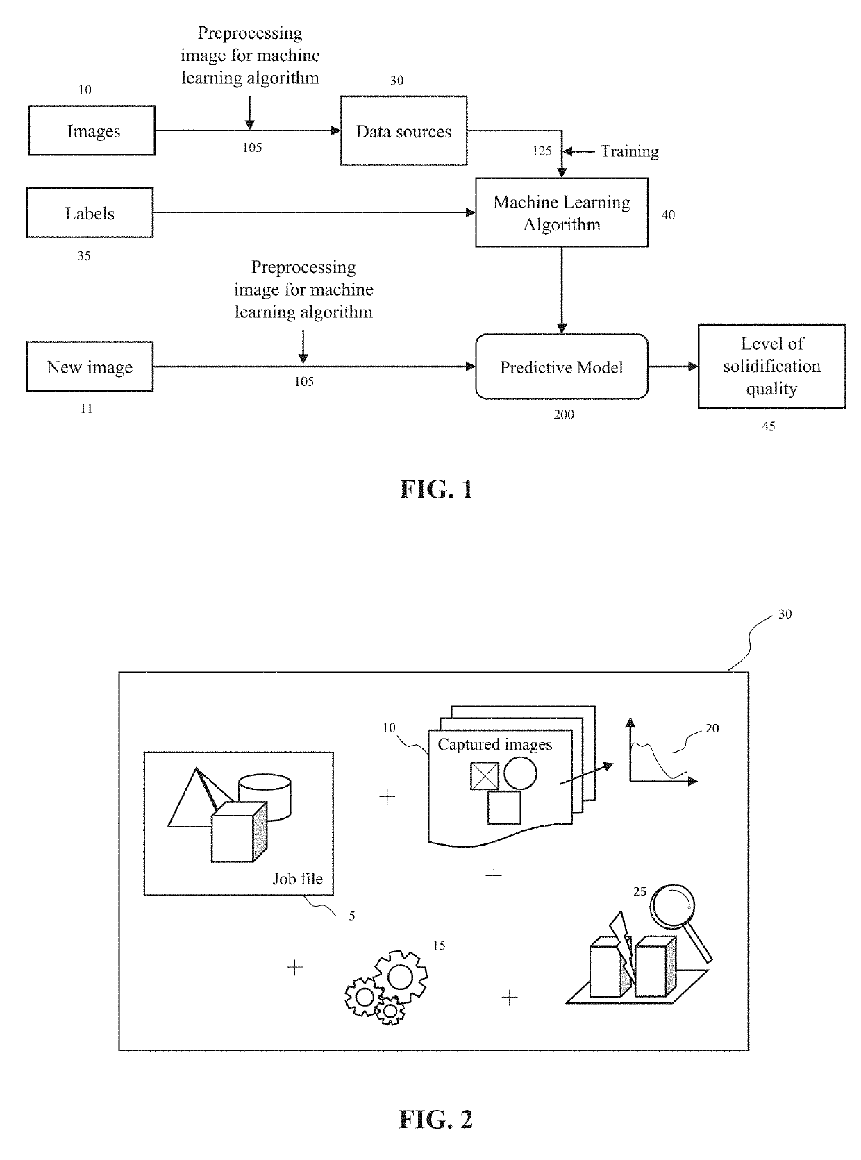
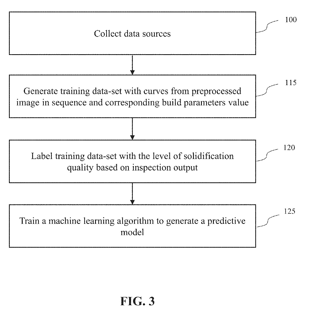
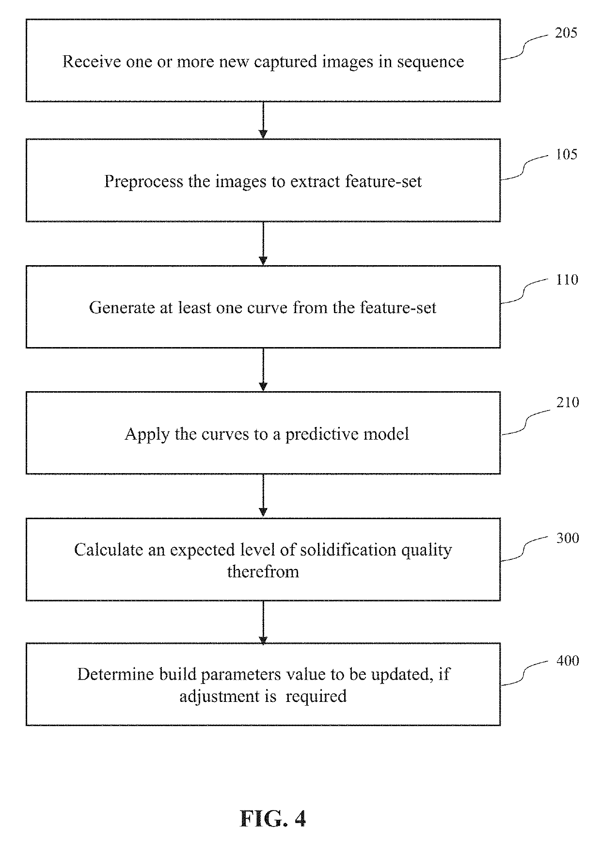
[0026]In the disclosed embodiment, based on the characteristics shown in captured images at predetermined setting in sequence, a predictive model is generated, which determines and predicts an estimated parameter value to be adjusted to correct by identifying the solidification quality of the scanned layer powder. The captured image of scanned layer powder during additive manufacturing process ...


PUM

PropertyMeasurementUnit
Temperatureaaaaaaaaaa
Areaaaaaaaaaaa
Heataaaaaaaaaa

Abstract

Systems and methods of monitoring solidification quality and automatic correcting any detected error in additive manufacturing are described. The present disclosure includes a build station for manufacturing one or more parts and a controller having one or more computer-vision based system coupled to the build station. One or more camera is provided to obtain a plurality of images of the solidified parts at predetermined settings. The present disclosure introduces a predictive model trained by machine learning algorithm, the predictive model calculates level of solidification quality of a manufactured part and build parameters value to be adjusted. The present disclosure introduces a plurality of validation coupons having various shapes to enhance more accuracy in manufacturing, wherein the validation coupons further include block data which is distributed to electronic ledger system.

Description

CROSS-REFERENCE TO A RELATED APPLICATION[0001]This application is a nonprovisional of claims the benefit of and priority to U.S. Provisional Patent Application No. 62 / 644,685, filed Mar. 19, 2018, inventors Ilgoo Hwang et al., titled “Quality Assurance Systems and Methods in Additive Manufacturing Process”, which is commonly assigned herewith, and all of which is hereby incorporated herein by reference in its entirety with the same full force and effect as if set forth in its entirety herein.FIELD OF THE INVENTION[0002]The present disclosure generally relates to systems and methods of monitoring additive manufacturing process via computer vision based system and, more particularly, to perform automated corrective actions in real-time using artificial intelligence.BACKGROUND OF THE INVENTION[0003]Additive manufacturing, as known as three-dimensional printing, is a technology that produces three-dimensional parts layer by layer from a powdered material which may be polymer or metal ba...

Claims


Application Information

Patent Timeline
IPC IPC(8): B29C64/393B22F3/105G05B17/02G06N3/08G06N20/00G06F17/50B29C64/153
CPCG06N3/08G06F17/50B29C64/393B33Y50/02B33Y10/00B29C64/153G06N20/00B22F2003/1057G05B17/02B22F3/1055B33Y30/00G01N21/8851G01N21/8806G01N2021/8883G01N2021/8411G05B13/048G05B2223/02G06F11/0736G06F11/3013G06F11/3058G06F11/0751Y02P10/25B22F12/17B22F12/49B22F10/38B22F12/67B22F10/32B22F10/28B22F12/44B22F12/52B22F2999/00B22F12/90B22F12/41B22F10/85G06N3/044G06N3/045B22F2203/03G06F30/00
Inventor HWANG, ILGOOYUN, JERALDYI, HON S.
Owner TYTUS3D SYST INC
Learn More