Power unit structure for electrically driven vehicle

a technology for power units and vehicles, applied in mechanical energy handling, electric propulsion mounting, transportation and packaging, etc., can solve the problems of high voltage parts exposed and increase design man-hours, and achieve the effect of reducing design man-hours, reducing service workload, and raising rigidity of units

Active Publication Date: 2019-09-19
HONDA MOTOR CO LTD
View PDF0 Cites 7 Cited by
  • Summary
  • Abstract
  • Description
  • Claims
  • Application Information

AI Technical Summary

Benefits of technology

[0006]The present invention has been made taking account of the above, and the object thereof is to provide a power unit structure for an electrically driven vehicle which can decrease design man-hours as well as raise the rigidity of the unit.
[0023]According to the present invention, it is possible to provide a power unit structure for an electrically driven vehicle which can decrease design man-hours as well as raise the rigidity of the unit.

Problems solved by technology

However, with the power unit structure of Patent Document 1, it is necessary to design so that each built-in gear and through hole of the three-phase power lines do not interfere, upon design of the transmission case, and thus there has been a problem in that the design man-hours increase.
In addition, the electric motor, transmission and inverter are fastened linearly to line up in a row; therefore, there has been a problem in being weak to external input from a direction orthogonal to the aligning direction, and a high voltage part is exposed during vehicle collision, etc.

Method used


Image

  • Power unit structure for electrically driven vehicle
  • Power unit structure for electrically driven vehicle
  • Power unit structure for electrically driven vehicle

Examples


Embodiment Construction

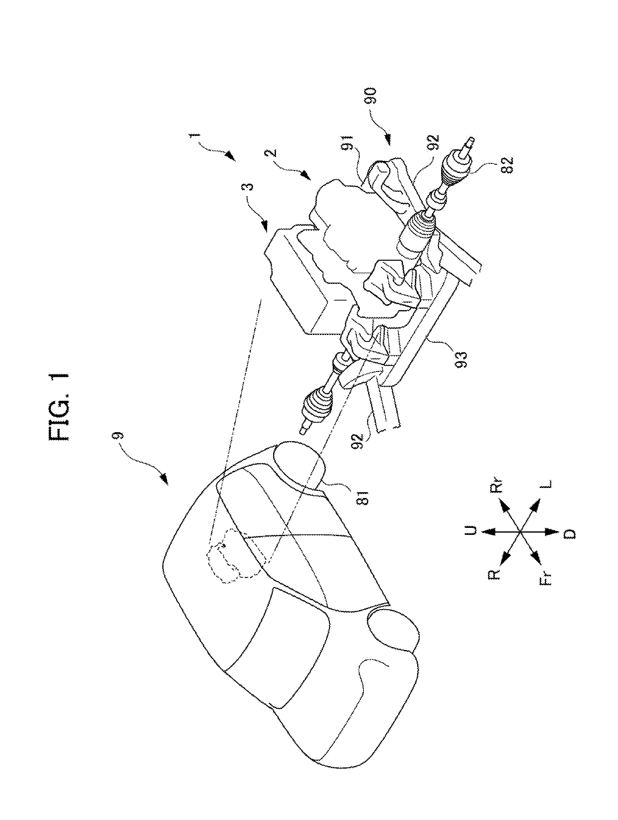
[0035]Hereinafter, an embodiment of the present invention will be explained in detail while referencing the drawings. It should be noted that, in the drawings, the U direction is up, D direction is down, Fr direction is vehicle forward, Rr is vehicle rearward, R direction is the right direction viewing from the driver's seat of the vehicle (vehicle width right side, and L direction is the left direction viewing from the driver's seat of the vehicle (vehicle width left side).

[0036]FIG. 1 is a perspective view showing the arrangement and outline configuration of a power unit structure 1 for an electrically driven vehicle 9 according to an embodiment of the present invention. As shown in FIG. 1, the power unit structure 1 for the electrically driven vehicle 9 according to the present embodiment is arranged at vehicle rearward (rear side) of the electrically driven vehicle 9. In addition, the power unit structure 1 for the electrically driven vehicle 9 according to the present embodimen...


PUM


Abstract

To provide a power unit structure for an electrically driven vehicle which can decrease design man-hours, as well as raise the rigidity of the unit. A control device unit for an electrically driven vehicle includes: a first mounting part which is a mounting part of a power supply unit that supplies electric power to an electric motor, and a second mounting part which fixes the control device unit to an electric motor unit; and the control device unit is mounted from a transmission case side of the electric motor unit towards an electric motor case side, the first mounting part being mounted to a central case, and the second mounting part being mounted to the transmission case.

Description

[0001]This application is based on and claims the benefit of priority from Japanese Patent Application No. 2018-045315, filed on 13 Mar. 2018,the content of which is incorporated herein by reference.BACKGROUND OF THE INVENTIONField of the Invention[0002]The present invention relates to a power unit structure for an electrically driven vehicle.Related Art[0003]Conventionally, a power unit structure of mechatronical integration type has been disclosed in which a transmission which converts the revolution of an electric motor is arranged along the axle direction between the electric motor and an inverter (control device) which performs rotation control of the electric motor (for example, refer to Patent Document 1). With this power unit structure, three-phase power lines connecting the electric motor and inverter are arranged to penetrate the transmission case.[0004]Patent Document 1: Japanese Unexamined Patent Application, Publication No. 2013-173425SUMMARY OF THE INVENTION[0005]Howev...

Claims


Application Information

Patent Timeline
Patent Type & Authority Applications(United States)
IPC IPC(8): B60K1/00H02K7/00H02K5/10H02K5/24H02K11/35
CPCH02K5/24H02K11/35H02K5/10B60K1/00H02K7/006B60K17/12B60K17/00B60K2001/001
Inventor SUZUKI, TAKANORIISHIHARA, YUYATOMINAGA, TAKURO
Owner HONDA MOTOR CO LTD
Why Eureka
Try Eureka