

Photochemically-assisted synthesis of layered birnessite (MNO2) nanosheets
a technology of birnessite and nanosheets, which is applied in the direction of positive electrodes, energy-based chemical/physical/physical-chemical processes, cell components, etc., can solve the problems of limited energy-efficient processes for synthesising mn(iv) oxides, and achieve the effect of enhancing the binding of -mno2 nanosheets
- Summary
- Abstract
- Description
- Claims
- Application Information
AI Technical Summary
Benefits of technology
Problems solved by technology
Method used
Image

Examples
Embodiment Construction
[0044]The disclosure may be understood by reference to the following detailed description, taken in conjunction with the drawings as described below. It is noted that, for purposes of illustrative clarity, certain elements in various drawings may not be drawn to scale.
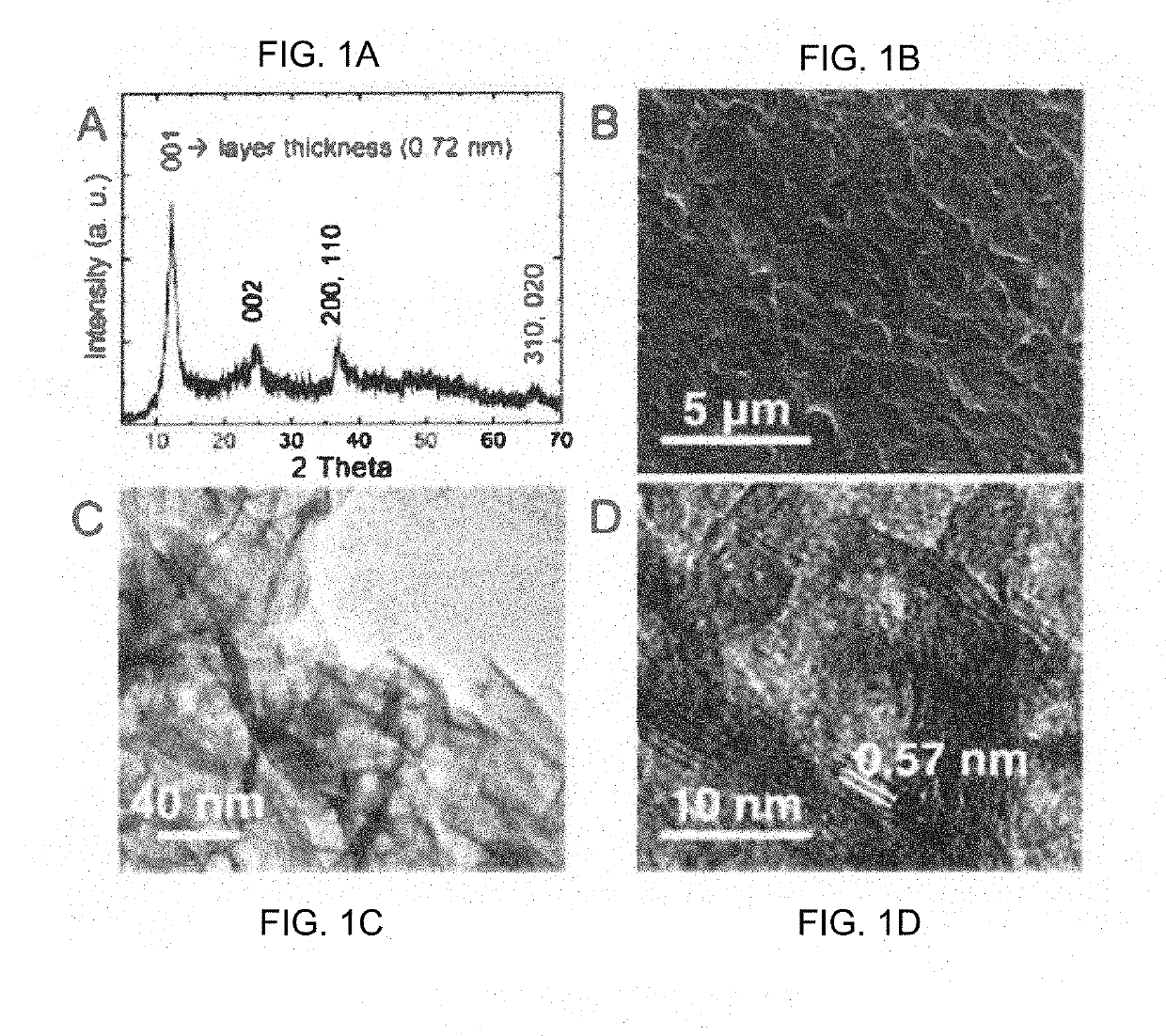
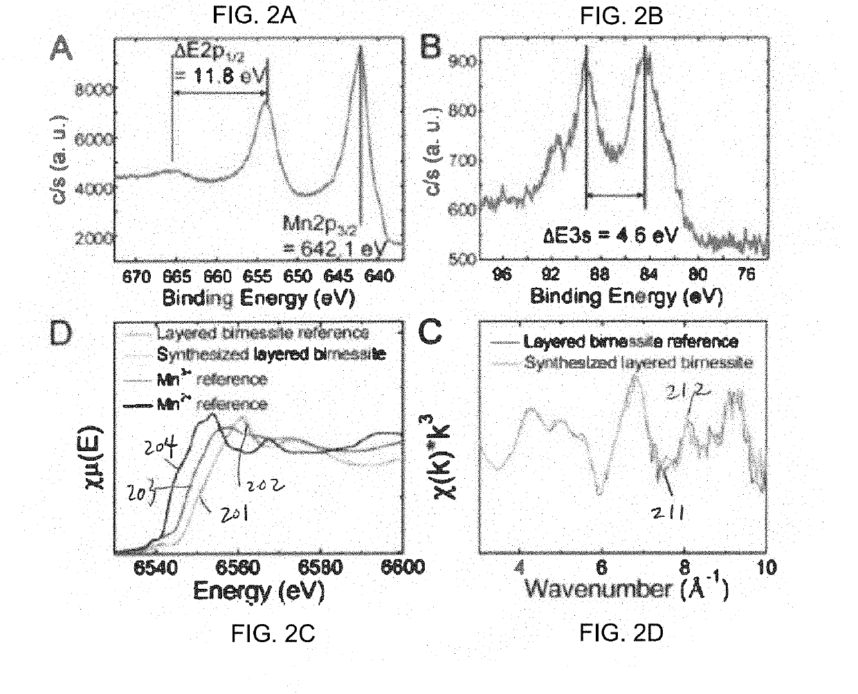
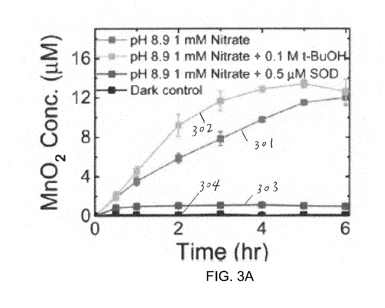
[0045]The present disclosure, using the photolysis of nitrate, provides the fast oxidation of Mn2+(aq) to Mn(IV)(s) and the formation of δ-MnO2 nanosheets with tunable thicknesses and structures. This environmentally relevant system forms δ-MnO2 nanosheets very fast comparable to microbial reactions. With the naturally abundant sources (i.e., nitrate and sunlight) and using generated reactive oxygen species, a sustainable chemical pathway to synthesize δ-MnO2 nanosheets is described. Also, the one-pot synthesis, can be beneficial to reduce production-cost in practical operation. After the synthesis reaction, a waste nitrate solution can be re-used by adding only Mn2+(aq). The reusable system can be helpful in saving op...
PUM
 Abstract
Description
Claims
Application Information