System for Testing Fluid Samples

a fluid sample and fluid technology, applied in the direction of direct flow property measurement, instruments, measurement devices, etc., can solve the problems of affecting the accuracy of measurement data, and generating significant was

Inactive Publication Date: 2019-09-19
AMETEK INC
View PDF13 Cites 0 Cited by
  • Summary
  • Abstract
  • Description
  • Claims
  • Application Information

AI Technical Summary

Problems solved by technology

As a result of their large size, conventional friction loops consume a considerable amount of electricity during operation (due to pumping the fluid), and generate significant waste (in the form of, at least, waste fluid).
Various convention

Method used


Image

  • System for Testing Fluid Samples

Examples


Embodiment Construction

[0008]Corresponding reference characters indicate corresponding parts throughout the several views. The exemplification set out herein illustrates an embodiment of the invention, in one form, and such exemplification is not to be construed as limiting the scope of the invention in any manner.

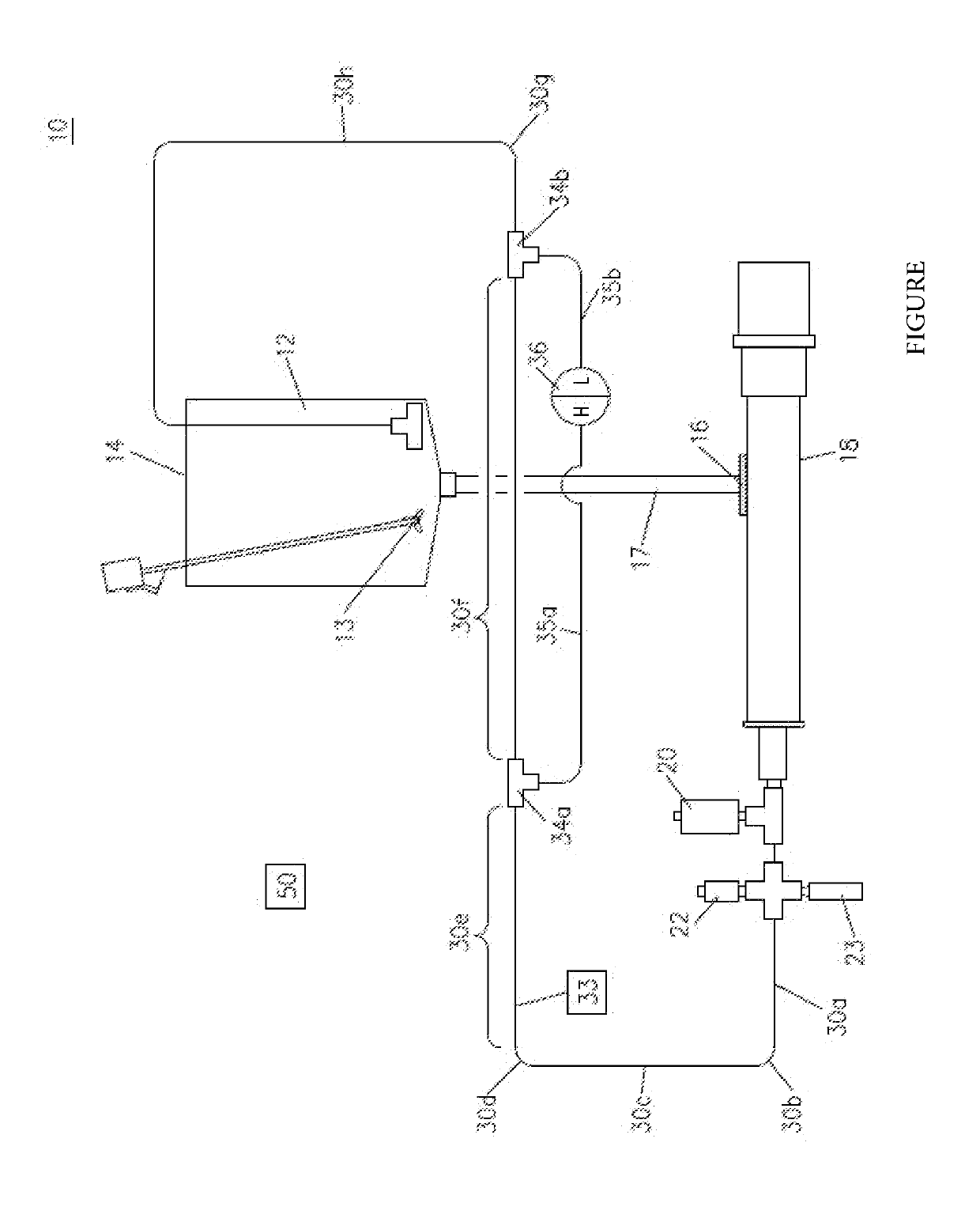
[0009]Referring now to the sole FIGURE, that FIGURE depicts a system 10 for testing fluids. The system 10 generally comprises a fluid preparation reservoir 12 (reservoir 12 hereinafter) for containing fluid. A mixer 13 is positioned in the reservoir 12 for mixing the fluid within the reservoir 12. The reservoir 12 includes an open end 14 for receiving fluid, and an outlet 16 for delivering fluid into a pump 18. The outlet 16 may be provided on the reservoir 12 itself, or a pipe 17 that is connected to the reservoir 12.

[0010]The outlet 19 of the pump 18 is fluidly connected to an apparatus 20 for flow conditioning and pulse damping the fluid delivered from the pump 18. The outlet of the apparatus...


PUM


Abstract

A system and method for measuring flow resistance of a fluid in a conduit is provided. The system generally includes a reservoir for containing the fluid, a pump connected to the reservoir for distributing the fluid through a conduit having a straight measurement section, one or more pressure sensors connected to the conduit for measuring the pressure of the fluid in the conduit at one end of the straight measurement section and an opposite end of the straight measurement section.

Description

FIELD OF THE INVENTION[0001]The present invention relates to a system for testing fluid samples. More particularly, the invention relates to a system for measuring the flow resistance of fluid samples.BACKGROUND OF THE INVENTION[0002]As is described in U.S. Patent App. Pub. No. 2014 / 0060175, which is incorporated herein by reference in its entirety, fluid flow through a pipe may incur resistance by friction between the flowing fluid and the interior surface of the pipe, turbulence in the flowing fluid, and deviations and / or restrictions in the flow path, among other factors. Pressure drop resulting from the resistance to flow may be determined by the use of a “friction loop.” A friction loop is a conduit through which a fluid under test flows. Pressure sensors can be connected to the conduit at spaced apart locations along the conduit. The measured differential pressure between the pressure sensors is related to the pressure drop in the conduit, and provides a direct measurement of ...

Claims


Application Information

Patent Timeline
IPC IPC(8): G01N11/08G01F7/00
CPCG01F7/005G01N11/08
Inventor CASTELL, DANIEL WILLIAMSTEELE, THOMASHICKS, THOMASWILLEMS, WILLIAM JOHN
Owner AMETEK INC
Why Eureka
Try Eureka