Fastener element

a technology of fastener and bending, which is applied in the field of fastener elements, can solve the problems of limiting the bending stiffness of the fastener element, and achieve the effect of increasing the shear stiffness of the corrugation

Active Publication Date: 2016-01-07
AB SKF
View PDF11 Cites 0 Cited by
  • Summary
  • Abstract
  • Description
  • Claims
  • Application Information

AI Technical Summary

Benefits of technology

[0008]The load area is thus located in a region of the fastener element where the corrugations are connected to the base part via the sidewalls and via the connection part between the sidewalls. Such a cross-section increases resistance to shear.
[0012]The fastener element comprises continuous reinforcement fibers that at least partly extend from the machine part to the axial end region remote from the machine part. Preferably, the continuous fibers extend completely from the machine part to the axial end region remote from the machine part. Due to the reduction in height of the corrugations, the continuous fibers in the corrugations are led down to the final section, which is at the same level as the base parts, where the load is applied. This creates a load path to the machine part which helps to maximize tension in the continuous fibers and minimize shear.
[0016]In a preferred embodiment, at least a part of the continuous reinforcement fibers extend from the machine part to the axial end region in a cross-wise manner. In other words, the continuous fibers have a longitudinal direction component and a transverse component, such that a particular fiber may form part of more than one corrugation before reaching the axial end region of the fastener element. The transverse direction component increases the shear stiffness of the corrugations.

Problems solved by technology

When the fastener element is made of a fiber-composite material, however, the bending moment can cause shear between the fibers, which limits the bending stiffness of the fastener element.

Method used


Image

  • Fastener element
  • Fastener element
  • Fastener element

Examples


Embodiment Construction

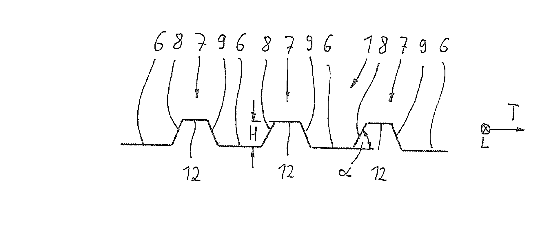
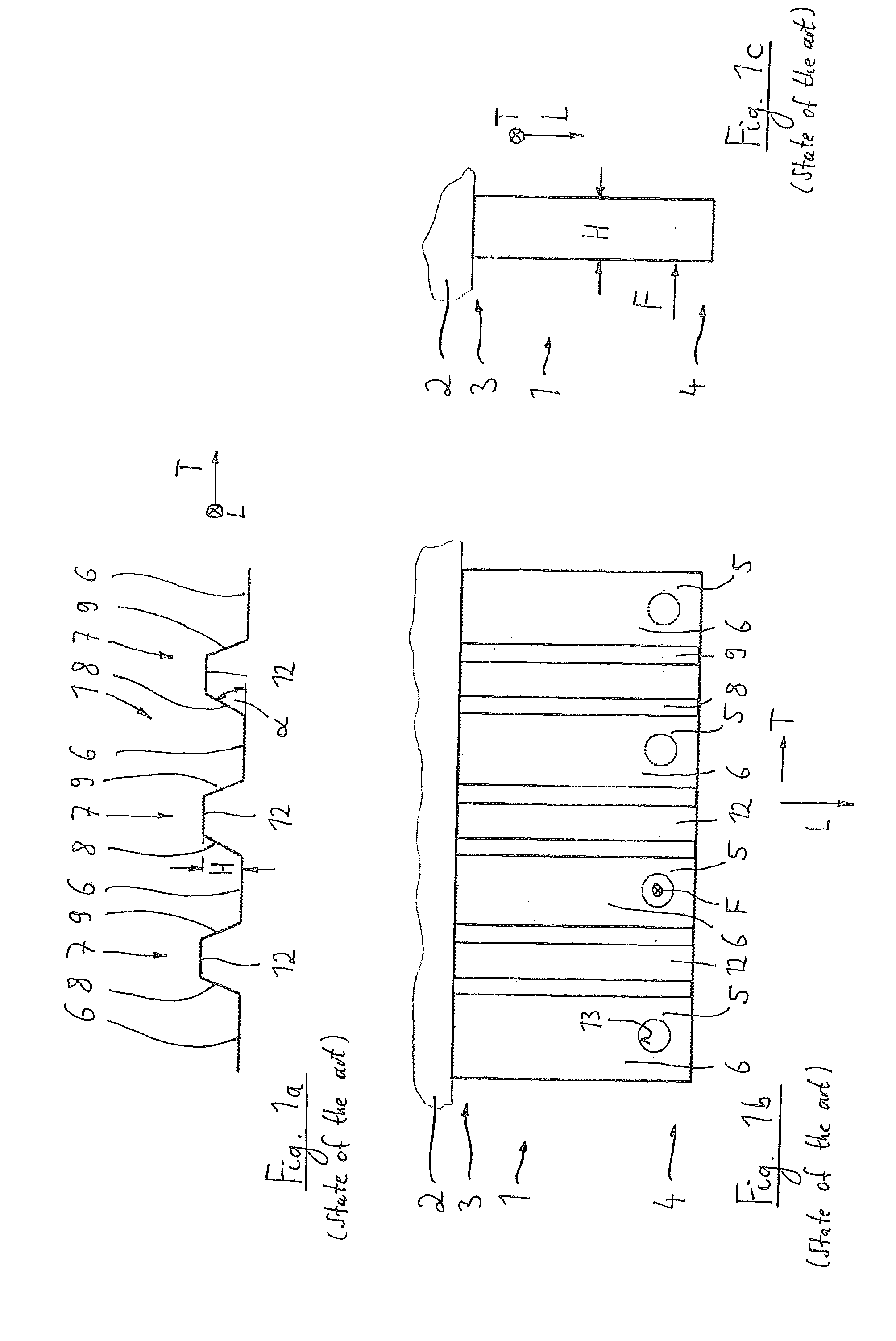
[0030]In FIGS. 1a, 1b and 1c, a known fastener element 1, made from a fibre-reinforced composite material, is shown.

[0031]The fastener element 1 extends generally in a longitudinal direction L as well as in a transverse direction T. It allows transmission of a load F (force) to a machine part 2. The fastener element is fixed at one of its axial end regions of its longitudinal extension, namely at its end region 3, with the machine part 2. The load F is acting on the fastener element 1 at the other axial end region 4 of the longitudinal extension in a load area 5. Furthermore, the fastener element 1 comprises a plurality of base parts 6 extending in the longitudinal direction L and having the load area 5; the base parts 6 are connected to each other by corrugations 7. Each corrugation 7 has two side walls 8 and 9 which extend under an angle □ from the base part 6. The side walls 8, 9 are joined by a connection part 12. These side walls 8, 9 have a height H, so that the fastener eleme...


PUM

PropertyMeasurementUnit
angleaaaaaaaaaa
angleaaaaaaaaaa
areaaaaaaaaaaa

Abstract

A fastener element for transmitting a load to a machine part. One of the fastener's longitudinal extension axial ends is fixed with the machine part. The load acts onto the fastener at the other longitudinal extension axial end in a load area. The fastener comprises a plurality of longitudinally extending base parts, including the load area. The base parts are connected to each other by corrugations. To reduce shear in the fastener, a height of the corrugations is substantially constant along a first extension in a fastener longitudinal direction, extending from the machine part to a transition region. The load area is arranged along a second extension in the fastener longitudinal direction adjoining the first extension. Along the second extension, the corrugations height is reduced from the transition region, becoming zero at a final section of the fastener in the axial end region remote from the machine part.

Description

CROSS REFERENCE TO RELATED APPLICATIONS[0001]This is a United States National Stage Application claiming the benefit of International Application Number PCT / EP2013 / 051356 filed on 24 Jan. 2013 (24.01.2013), which is incorporated herein by reference in its entirety.TECHNICAL FIELD[0002]The invention relates to a fastener element extending in a longitudinal direction and in a transverse direction for transmitting a load to a machine part, wherein the fastener element is fixed at one of its axial end regions of its longitudinal extension with the machine part, wherein the load is acting on the fastener element at the other axial end region of its longitudinal extension in a load area, wherein the fastener element comprises a plurality of base parts extending in the longitudinal direction and having the load area, wherein the base parts are connected to each other by corrugations, wherein each corrugation has two side walls extending under an angle from the base part and having a height...

Claims


Application Information

Patent Timeline
Patent Type & Authority Applications(United States)
IPC IPC(8): F16B5/00
CPCF16B5/0012B29L2016/00B29C70/222F16B5/0614
Inventor SCHAAKE, RICHARD
Owner AB SKF
Why Eureka
Try Eureka