Light-Guiding System, especially for the Lighting of Land Transport Means

a technology of light guiding and land transport, which is applied in the direction of mechanical equipment, lighting and heating equipment, instruments, etc., can solve the problems of increased light transmission, increased negative influence of the position of the light source, and large drop in efficiency

Inactive Publication Date: 2019-09-19
VARROC LIGHTING SYST SRO
View PDF9 Cites 6 Cited by
  • Summary
  • Abstract
  • Description
  • Claims
  • Application Information

AI Technical Summary

Problems solved by technology

However, this only applies if the light source is placed in a suitable position relative to both the light guide and the direction in which the light from the light guide system is to be coupled out.
The problem arises in situations when it is not possible to place the light source in the assembly of the system in a suitable position to ensure the coupling-out of the light in the desired direction by means of the coupling-out optics.
Instead, a significant amount of light is reflected or refracted in a completely different direction than is required, and such a solution is accompanied by light loss and a large drop in efficiency.
Moreover, if it is required that the light guide be substantially curved in a direction or, more specifically, in the plane in which the light from the light guide is to be coupled out, the negative influence of the position of the light source is even greater.
The disadvantage of this solution is the fact that if the light guide has a greater curvature in the direction of the light being

Method used


Image

  • Light-Guiding System, especially for the Lighting of Land Transport Means
  • Light-Guiding System, especially for the Lighting of Land Transport Means
  • Light-Guiding System, especially for the Lighting of Land Transport Means

Examples


Embodiment Construction

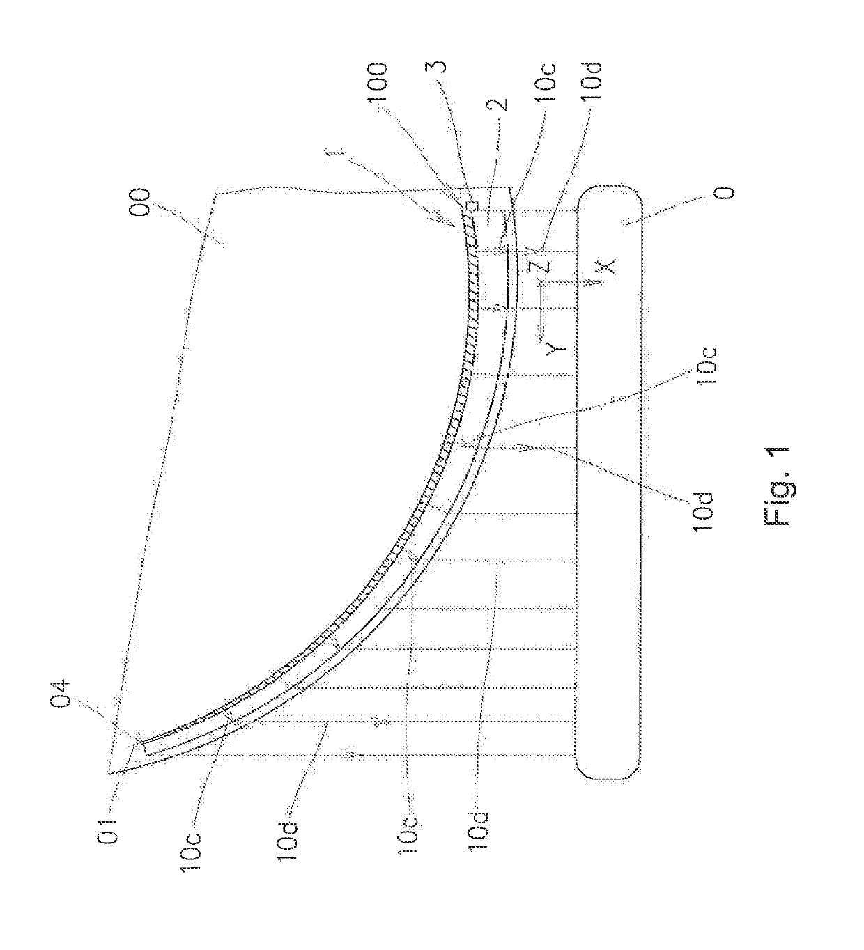
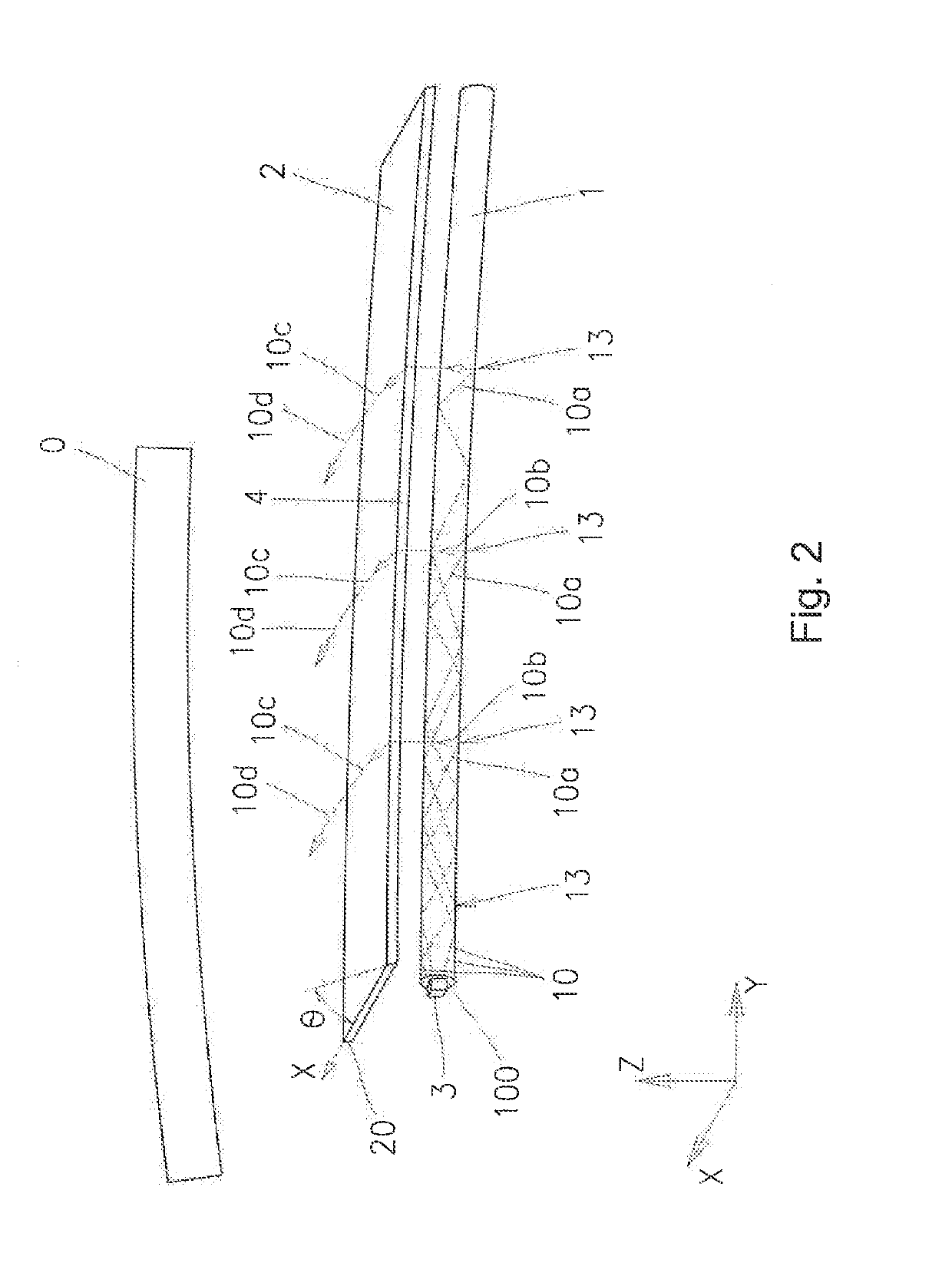
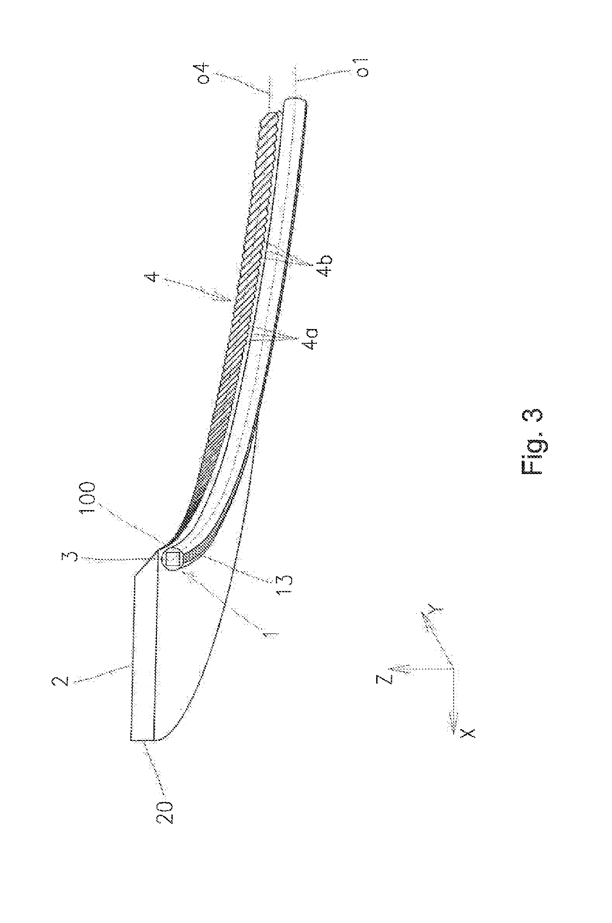
[0017]The invention will be described with reference to exemplary embodiments of a light guiding system for motor vehicles which has a pre-determined direction X of the light radiation into the target illuminated area O in front of the light guiding system. The light guiding system is arranged in a cover 00.

[0018]The light guiding system comprises a line light guide 1, which is arranged in the X-Y plane of the Cartesian coordinate system and is curved around the Z axis. The bend of the line light guide 1 is either circular, i.e. with a constant radius, or non-circular, i.e. with a variable radius, e.g. in the shape of a suitable curve, e.g., a conic section, or the light guide 1 has a generally curved shape according to current requirements. To make use of the present invention, it is important for the bend of the line light guide 1 to be greater than the maximum bend allowing to couple out the light guided within the line light guide 1 by total internal reflection directly in the d...


PUM


Abstract

The invention relates to a light guiding system, especially for the lighting of land transport means, which comprises a line light guide (1), one end of which is associated with a light source (3), whereby the line light guide (1) is along its length provided with a coupling out surface (13) of light, opposite which is arranged an inclined reflective wall (4) directing the light coupled out of the line light guide (1) into a radiating body (2), from which the light comes out in a desired direction (X, 10 d). The line light guide (1) is longitudinally curved and the coupling-out surface (13) of the light guide (1) is arranged in a plane parallel to the plane of the curvature of the light guide (1), whereby the inclined reflective wall (4) follows the curvature of the light guide (1) and is along its length along the line light guide (1) provided with reflective directing surfaces (4a) which are adapted to reflect the beams (10b) to the plane of the light output and at the same time to a direction (10c) which corresponds to the light emitted at the output surface (20) of the radiating body (2) to the required resulting direction (X) of the light beams (10d) along the entire length of the inclined reflective wall (4).

Description

TECHNICAL FIELD[0001]The invention relates to a light guiding system, especially for the lighting of land transport means, which includes a line light guide, whose one end is associated with a light source, whereby the line light guide is along its length provided with a coupling-out surface of light, against which is arranged an inclined reflective wall directing the light coupled out of the line light guide to a radiating body, from which the light is emitted in a desired direction.BACKGROUND ART[0002]The use of light guides for the lighting of land transport means as such is well-known. Light guides allow the light to be transmitted from a light source to a point of light output and to be coupled out in a desired direction, which makes it possible to realize a variety of previously infeasible design and shape solutions of the light output arrangement while maintaining the homogeneity and power of the output light beam. In light guides, the light is guided longitudinally by total ...

Claims


Application Information

Patent Timeline
IPC IPC(8): F21V8/00
CPCG02B6/0008B60Q1/00B60Q3/00F21S41/141G02B6/0018G02B6/0038G02B6/0073G02B6/0078F21S43/235G02B6/001G02B6/0016G02B6/0028G02B6/0031
Inventor GLOSS, TOMASHENDRYCH, ALESHRUSKA, JAKUB
Owner VARROC LIGHTING SYST SRO
Why Eureka
Try Eureka