
Capacitor and method for manufacturing the same

a technology of capacitors and capacitors, applied in the manufacture of electrolytic capacitors, capacitor dielectric layers, fixed capacitor details, etc., can solve the problems of deterioration in the withstand voltage of capacitors, inability to achieve both sufficient electrostatic capacitance and strength, and difficulty in obtaining sufficient electrostatic capacitance, etc., to achieve high specific surface area, high electrostatic capacitance, and high strength

Active Publication Date: 2020-01-28
MURATA MFG CO LTD
View PDF18 Cites 0 Cited by
  • Summary
  • Abstract
  • Description
  • Claims
  • Application Information

AI Technical Summary

Benefits of technology

[0010]It is an object of the present invention to provide a capacitor having a high electrostatic capacitance and high strength, including a sintered body as a conductive base material with high specific surface area.
[0011]The present inventors have intensively studied the problems described above to find that the combination use of a plurality of kinds of metal powders enables both of sufficient electrostatic capacitance and strength to be achieved without including a metal support, so that the problem of (1) can be solved; and the combination use also enables firing at relatively low temperature, so that the problem of (2) can be solved. In addition, they have found that roughening of a surface of a metal support, or provision of a low melting-point metal to the surface of the metal support enables the metal support and a sintered body to be bonded to each other with sufficient strength, so that the problem of (3) can be solved.
[0014]According to the present invention, when a metal sintered body is formed together with a plurality of kinds of metal powders in a capacitor including the metal sintered body as a conductive base material with high specific surface area, sufficient electrostatic capacitance and intensity can be obtained. In addition, when the conductive base material with high specific surface area is obtained by disposing metal powders on a metal support and firing the metal powders, the metal support and the sintered body can be bonded to each other with sufficient strength by roughening a surface of the metal support, or by providing low melting-point metal to the surface of the metal support.

Problems solved by technology

Existence of such impurities in the pores may cause troubles, such as deterioration in withstand voltage of the capacitor, and the like.
(1) Simple sintering of metal powders cannot achieve both sufficient electrostatic capacitance and strength.
However, as the sintering of the metal powders progresses, pores of a metal sintered body crush to make sufficient electrostatic capacitance difficult to be obtained.
Meanwhile, in order to obtain a conductive base material with high specific surface area that provides a sufficient electrostatic capacitance, the metal powders need to be treated at low temperature so that sintering does not progress much to maintain pores of a metal sintered body.
However, when the sintering is insufficient, sufficient strength cannot be secured.
(2) In addition, when a metal sintered body is formed on a metal support in order to secure its strength, the metal support may be warped due to shrinkage during sintering of metal powders.

Method used


Image

  • Capacitor and method for manufacturing the same
  • Capacitor and method for manufacturing the same
  • Capacitor and method for manufacturing the same

Examples


example 1

[0158]Ni powders and Cu powders having an average grain diameter shown in Table 1 were prepared. A metal raw material 1 shown in Table 1 was mixed alone, or mixed with a metal raw material 2 in a predetermined ratio, and was dispersed in ethanol by ball milling with use of zirconia balls each having a diameter of 1 mm. Polyvinyl alcohol was added to this dispersion liquid to prepare metal powder slurries corresponding to sample numbers 1 to 16.

[0159]A metal powder layer was formed on a flat alumina substrate by a doctor blade method, using the slurry described above, so as to have a thickness of about 100 μm after being dried. This sample was degreased at 200° C. to 300° C. in a firing furnace, and then was heat treated at 300° C. to 650° C. for 5 minutes in an N2 atmosphere to obtain a metal sintered body. The metal sintered body did not stick to the alumina substrate and could be separated from the alumina substrate as a metal sintered body.

[0160]This metal sintered body was used ...

example 2

[0170]Ni powders and Cu powders having an average grain diameter shown in Table 2 were prepared. A metal raw material 1 shown in Table 2 alone or mixed with a metal raw material 2 in a predetermined ratio was dispersed in ethanol by ball milling with use of zirconia balls each having a diameter of 1 mm. Polyvinyl alcohol was added to this dispersion liquid to prepare metal powder slurries corresponding to sample numbers 21 to 35.

[0171]Meanwhile, a Ni foil and a Cu foil were prepared as a metal support, and were dipped in an alkaline solution so that surface treatment was applied to each metal foil. Then, a surface of each metal foil was roughened with a sulfuric acid-hydrogen peroxide type etching agent while treatment time was changed.

[0172]The slurry described above was applied to the Ni foil and the Cu foil by a doctor blade method to form a metal powder layer such that the metal powder layer after drying had a thickness of about 50 μm. This sample was degreased at 200° C. to 300...

example 3

[0183]Ni powders and Cu powders having an average grain diameter shown in Table 3 were prepared. A metal raw material 1 shown in Table 3 alone or mixed with a metal raw material 2 in a predetermined ratio was dispersed in ethanol by ball milling with use of zirconia balls each having a diameter of 1 mm. Polyvinyl alcohol was added to this dispersion liquid to prepare metal powder slurries corresponding to sample numbers 41 to 56.

[0184]Meanwhile, a Ni foil with a thickness of 10 μm (sample numbers 41 to 53) provided with a non-roughened surface and a Ni foil with a thickness of 10 μm (sample number 54) provided with a surface that is roughened so as to have a distance between recesses of 0.15 μm were prepared as a support. In addition, an epoxy resin was applied to a flat glass plate by spin coating, and a Ni metal layer with a thickness of 0.5 μm was formed by sputtering to prepare a support (the sample number 55). Further, an epoxy resin was applied to a flat glass plate by spin co...


PUM

PropertyMeasurementUnit
porosityaaaaaaaaaa
melting pointaaaaaaaaaa

Abstract

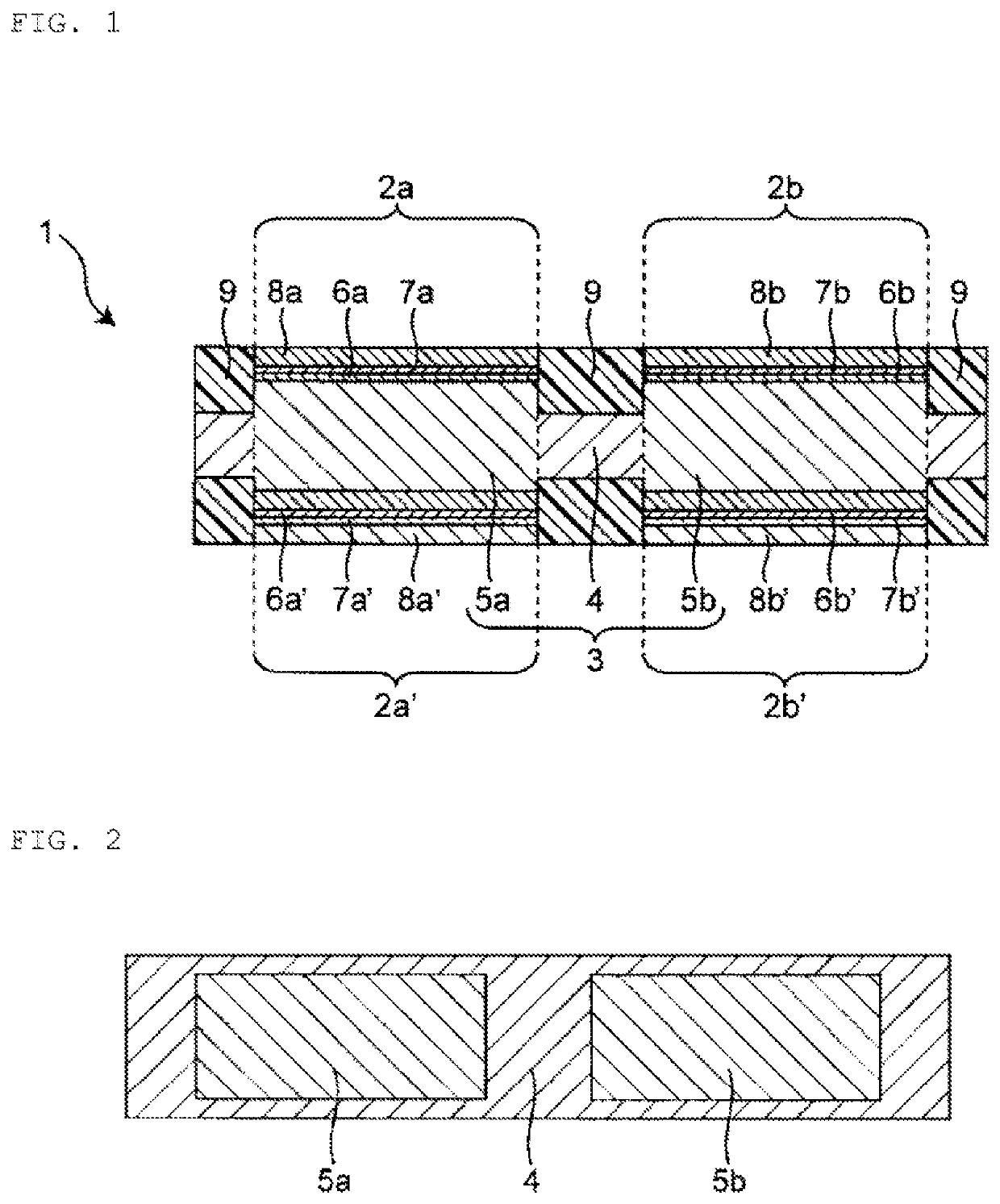
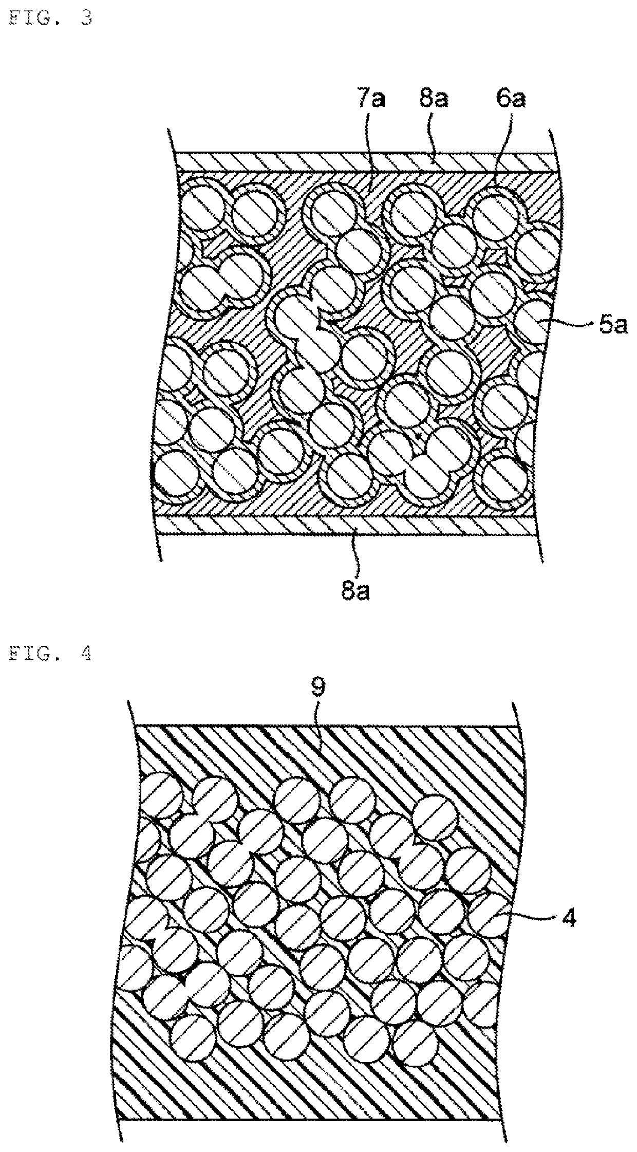
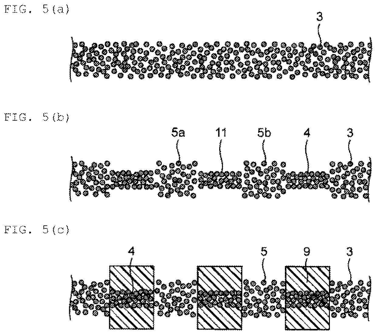
A capacitor that includes a conductive base material with high specific surface area, a dielectric layer covering the conductive base material with high specific surface area, and an upper electrode covering the dielectric layer, in which the conductive base material with high specific surface area is formed of a metal sintered body as a whole.

Description

CROSS REFERENCE TO RELATED APPLICATIONS[0001]The present application is a continuation of International application No. PCT / JP2016 / 072518, filed Aug. 1, 2016, which claims priority to Japanese Patent Application No. 2015-159581, filed Aug. 12, 2015, the entire contents of each of which are incorporated herein by reference.FIELD OF THE INVENTION[0002]The present invention relates to a capacitor and a method for manufacturing the capacitor.BACKGROUND OF THE INVENTION[0003]In recent years, capacitors having higher electrostatic capacitance have been required as electronic devices are mounted with high density. As such a capacitor, Patent Document 1 discloses an electrolytic capacitor including a high specific surface area aluminum foil made porous by etching treatment, for example.[0004]Patent Document 1: Japanese Unexamined Patent Application Publication No. 2009-270140SUMMARY OF THE INVENTION[0005]As described in Patent Document 1, a method for etching a metal foil is known as a meth...

Claims


Application Information

Patent Timeline
Patent Type & Authority Patents(United States)
IPC IPC(8): H01G4/30H01G4/06
CPCH01G4/06H01G4/30H01G4/33H01G9/052H01G4/306H01G9/0032H01G9/0525H01G9/07H01G4/008H01G4/085
Inventor INOUE, NORIYUKIARAKAWA, TAKEOAOKI, KENSUKESAEKI, HIROMASAKANRYO, KOICHITSURU, AKIHIROMORI, HARUHIKO
Owner MURATA MFG CO LTD
Learn More